

Question: Question 1 ( CLO 1 and 2 ) a ) The top girder of the portal frame shown below in Figure 1 is subjected to
Question CLO and
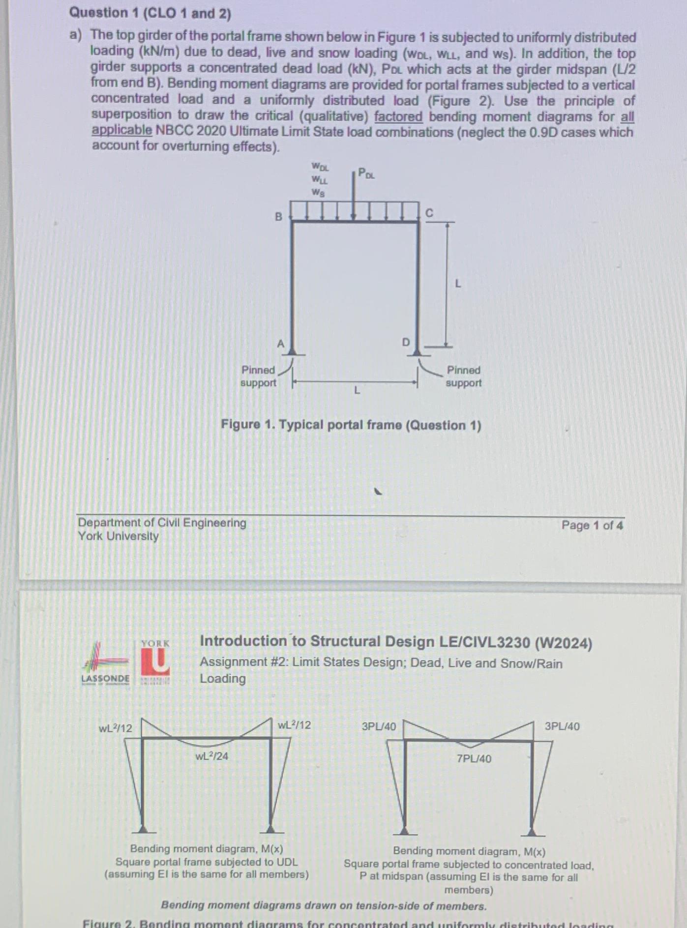
a The top girder of the portal frame shown below in Figure is subjected to uniformly distributed loading due to dead, live and snow loading and : In addition, the top girder supports a concentrated dead load Pou which acts at the girder midspan L from end B Bending moment diagrams are provided for portal frames subjected to a vertical concentrated load and a uniformly distributed load Figure Use the principle of superposition to draw the critical qualitative factored bending moment diagrams for all applicable NBCC Ultimate Limit State load combinations neglect the D cases which account for overturning effects
Figure Typical portal frame Question
Department of Clvil Engineering
Page of
York University
Introduction to Structural Design LECIVLW
Assignment #: Limit States Design; Dead, Live and SnowRain Loading
benaing moment alagram, Square portal frame subjected to UDL assuming is the same for all members
Bending moment diagram,
Square portal frame subjected to concentrated load, at midspan assuming is the same for all members
Bending moment diagrams drawn on tensionside of members.
Step by Step Solution
There are 3 Steps involved in it
1 Expert Approved Answer
Step: 1 Unlock

Question Has Been Solved by an Expert!
Get step-by-step solutions from verified subject matter experts
Step: 2 Unlock
Step: 3 Unlock