

Question: Question 2 Consider the 3-joint robot illustrated in Figure 2 below. The location and di- rection of the joints in the home configuration of the
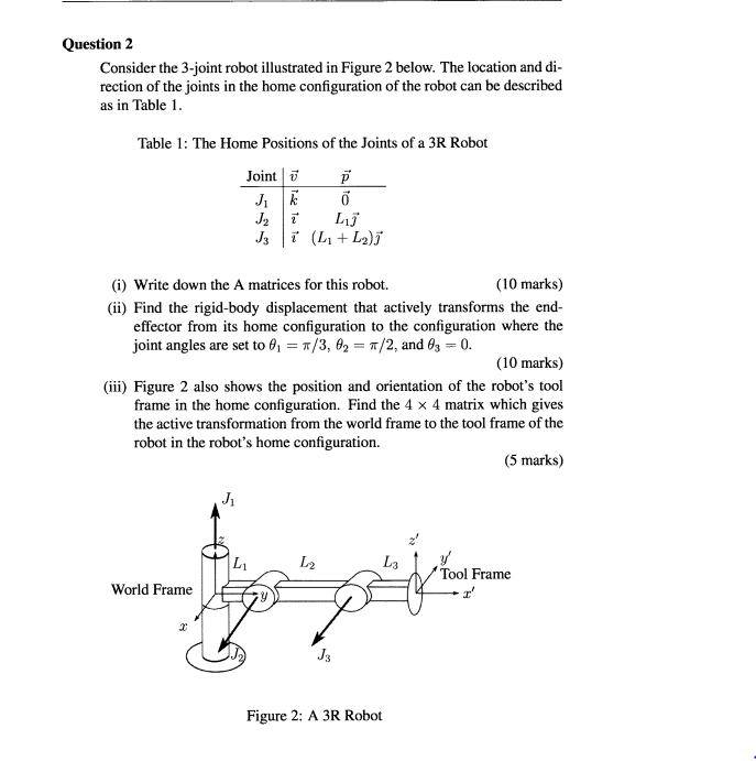
Question 2 Consider the 3-joint robot illustrated in Figure 2 below. The location and di- rection of the joints in the home configuration of the robot can be described as in Table 1. Table 1: The Home Positions of the Joints of a 3R Robot Joint v JR 0 J2 T Lj J3 i (L +L2) (1) Write down the A matrices for this robot. (10 marks) (ii) Find the rigid-body displacement that actively transforms the end- effector from its home configuration to the configuration where the joint angles are set to 6, = */3, 4, = */2, and 63 = 0. (10 marks) (iii) Figure 2 also shows the position and orientation of the robot's tool frame in the home configuration. Find the 4 x 4 matrix which gives the active transformation from the world frame to the tool frame of the robot in the robot's home configuration. (5 marks) J L L2 L y 'Tool Frame I World Frame 2 J3 Figure 2: A 3R Robot
Step by Step Solution
There are 3 Steps involved in it

Get step-by-step solutions from verified subject matter experts