

Question: Question 4 35 Marks (a) The dynamical equations in synchronous (da) frame for a Permanent Magnet Synchronous Motor (PMSM) in usual notation. Figure Q4 (a)
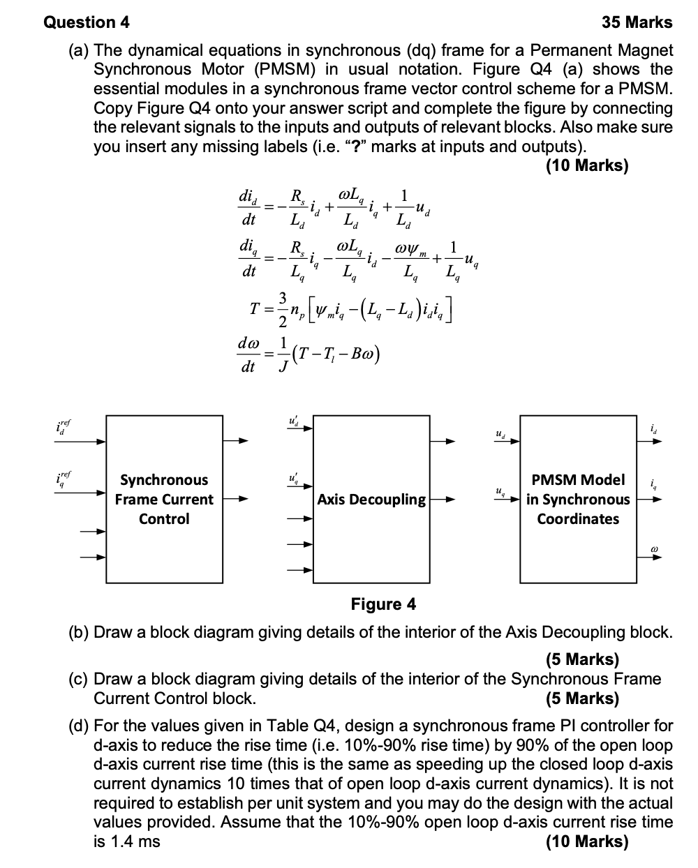
Question 4 35 Marks (a) The dynamical equations in synchronous (da) frame for a Permanent Magnet Synchronous Motor (PMSM) in usual notation. Figure Q4 (a) shows the essential modules in a synchronous frame vector control scheme for a PMSM. Copy Figure Q4 onto your answer script and complete the figure by connecting the relevant signals to the inputs and outputs of relevant blocks. Also make sure you insert any missing labels (i.e. ? marks at inputs and outputs). (10 Marks) did R in + ud dt La La L die dt LA La La T= [ymi, -(1, -L, )icia] do (T-1 dt J 1 R m 1 + u La 3 n p 2 1 inter u u u Synchronous Frame Current Control Axis Decoupling PMSM Model in Synchronous Coordinates Figure 4 (b) Draw a block diagram giving details of the interior of the Axis Decoupling block. (5 Marks) (c) Draw a block diagram giving details of the interior of the Synchronous Frame Current Control block. (5 Marks) (d) For the values given in Table Q4, design a synchronous frame Pl controller for d-axis to reduce the rise time (i.e. 10%-90% rise time) by 90% of the open loop d-axis current rise time (this is the same as speeding up the closed loop d-axis current dynamics 10 times that of open loop d-axis current dynamics). It is not required to establish per unit system and you may do the design with the actual values provided. Assume that the 10%-90% open loop d-axis current rise time is 1.4 ms (10 Marks) Question 4 35 Marks (a) The dynamical equations in synchronous (da) frame for a Permanent Magnet Synchronous Motor (PMSM) in usual notation. Figure Q4 (a) shows the essential modules in a synchronous frame vector control scheme for a PMSM. Copy Figure Q4 onto your answer script and complete the figure by connecting the relevant signals to the inputs and outputs of relevant blocks. Also make sure you insert any missing labels (i.e. ? marks at inputs and outputs). (10 Marks) did R in + ud dt La La L die dt LA La La T= [ymi, -(1, -L, )icia] do (T-1 dt J 1 R m 1 + u La 3 n p 2 1 inter u u u Synchronous Frame Current Control Axis Decoupling PMSM Model in Synchronous Coordinates Figure 4 (b) Draw a block diagram giving details of the interior of the Axis Decoupling block. (5 Marks) (c) Draw a block diagram giving details of the interior of the Synchronous Frame Current Control block. (5 Marks) (d) For the values given in Table Q4, design a synchronous frame Pl controller for d-axis to reduce the rise time (i.e. 10%-90% rise time) by 90% of the open loop d-axis current rise time (this is the same as speeding up the closed loop d-axis current dynamics 10 times that of open loop d-axis current dynamics). It is not required to establish per unit system and you may do the design with the actual values provided. Assume that the 10%-90% open loop d-axis current rise time is 1.4 ms (10 Marks)
Step by Step Solution
There are 3 Steps involved in it

Get step-by-step solutions from verified subject matter experts