

Question: Question 4 ( 8 points ) Design the finite state machine with input x and output z described by the state diagrams shown below: input
Question points
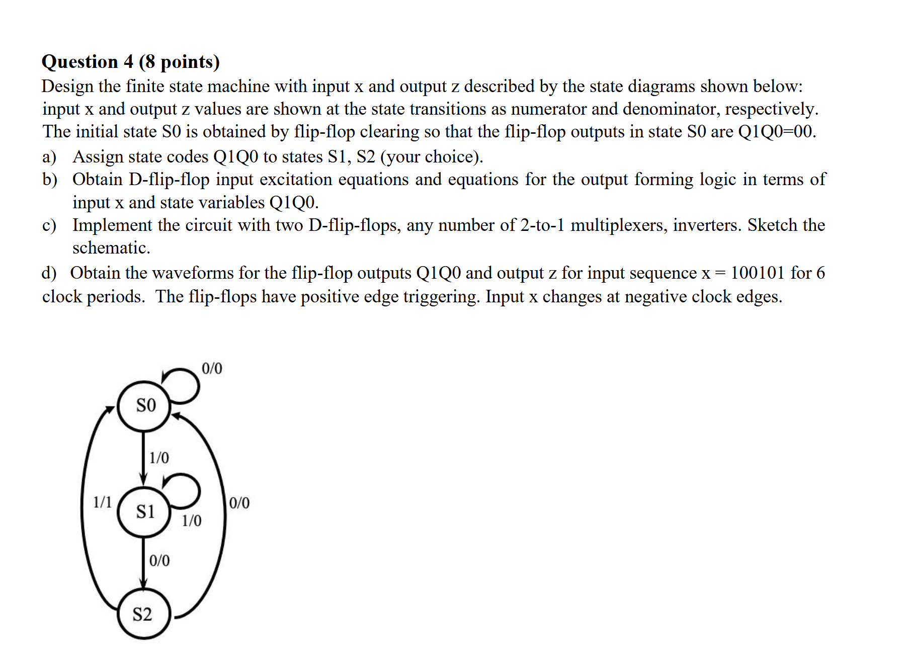
Design the finite state machine with input x and output z described by the state diagrams shown below: input x and output z values are shown at the state transitions as numerator and denominator, respectively. The initial state S is obtained by flipflop clearing so that the flipflop outputs in state S are mathrmQmathrmQ
a Assign state codes QQ to states S Syour choice
b Obtain Dflipflop input excitation equations and equations for the output forming logic in terms of input x and state variables QQ
c Implement the circuit with two Dflipflops, any number of to multiplexers, inverters. Sketch the schematic.
d Obtain the waveforms for the flipflop outputs QQ and output z for input sequence mathrmx for clock periods. The flipflops have positive edge triggering. Input x changes at negative clock edges.
Step by Step Solution
There are 3 Steps involved in it
1 Expert Approved Answer
Step: 1 Unlock

Question Has Been Solved by an Expert!
Get step-by-step solutions from verified subject matter experts
Step: 2 Unlock
Step: 3 Unlock