

Question: Question # 4 : The figure below depicts steady state flow through a non - uniform column consisting of two distinct materials where each soil
Question #:
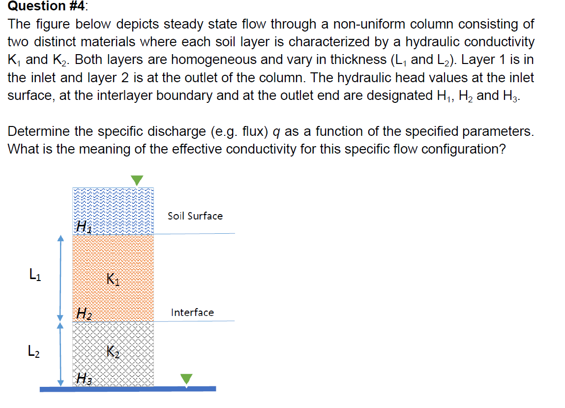
The figure below depicts steady state flow through a nonuniform column consisting of
two distinct materials where each soil layer is characterized by a hydraulic conductivity
K and K Both layers are homogeneous and vary in thickness L and L Layer is in
the inlet and layer is at the outlet of the column. The hydraulic head values at the inlet
surface, at the interlayer boundary and at the outlet end are designated H H and H
Determine the specific discharge eg flux q as a function of the specified parameters.
What is the meaning of the effective conductivity for this specific flow configuration?Question #:
The figure below depicts steady state flow through a nonuniform column consisting of
two distinct materials where each soil layer is characterized by a hydraulic conductivity
and Both layers are homogeneous and vary in thickness and : Layer is in
the inlet and layer is at the outlet of the column. The hydraulic head values at the inlet
surface, at the interlayer boundary and at the outlet end are designated and
Determine the specific discharge eg flux as a function of the specified parameters.
What is the meaning of the effective conductivity for this specific flow configuration?
Step by Step Solution
There are 3 Steps involved in it
1 Expert Approved Answer
Step: 1 Unlock

Question Has Been Solved by an Expert!
Get step-by-step solutions from verified subject matter experts
Step: 2 Unlock
Step: 3 Unlock