

Question: Recently got this in an e x a m, just looking to see if I went right with it Question 3 (a) Apply your knowledge
Recently got this in an e x a m, just looking to see if I went right with it
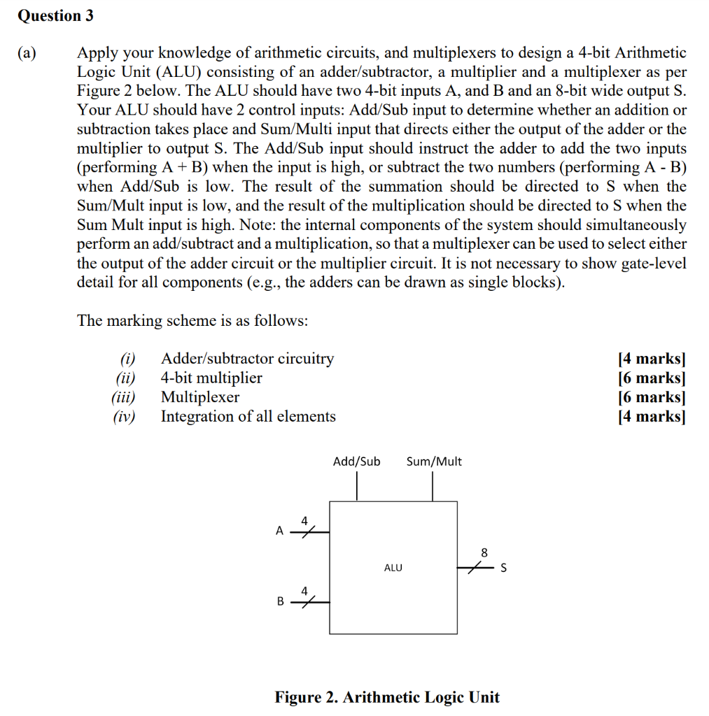
Question 3 (a) Apply your knowledge of arithmetic circuits, and multiplexers to design a 4-bit Arithmetic Logic Unit (ALU) consisting of an adder/subtractor, a multiplier and a multiplexer as per Figure 2 below. The ALU should have two 4-bit inputs A, and B and an 8-bit wide output S. Your ALU should have 2 control inputs: Add/Sub input to determine whether an addition or subtraction takes place and Sum/Multi input that directs either the output of the adder or the multiplier to output S. The Add/Sub input should instruct the adder to add the two inputs (performing A + B) when the input is high, or subtract the two numbers (performing A - B) when Add/Sub is low. The result of the summation should be directed to S when the Sum/Mult input is low, and the result of the multiplication should be directed to S when the Sum Mult input is high. Note: the internal components of the system should simultaneously perform an add/subtract and a multiplication, so that a multiplexer can be used to select either the output of the adder circuit or the multiplier circuit. It is not necessary to show gate-level detail for all components (e.g., the adders can be drawn as single blocks). The marking scheme is as follows: (i) (ii) Adder/subtractor circuitry 4-bit multiplier Multiplexer Integration of all elements [4 marks] [6 marks] [6 marks] [4 marks) (iii) (iv) Add/Sub Sum/Mult A 8 ALU S B4 Figure 2. Arithmetic Logic Unit Question 3 (a) Apply your knowledge of arithmetic circuits, and multiplexers to design a 4-bit Arithmetic Logic Unit (ALU) consisting of an adder/subtractor, a multiplier and a multiplexer as per Figure 2 below. The ALU should have two 4-bit inputs A, and B and an 8-bit wide output S. Your ALU should have 2 control inputs: Add/Sub input to determine whether an addition or subtraction takes place and Sum/Multi input that directs either the output of the adder or the multiplier to output S. The Add/Sub input should instruct the adder to add the two inputs (performing A + B) when the input is high, or subtract the two numbers (performing A - B) when Add/Sub is low. The result of the summation should be directed to S when the Sum/Mult input is low, and the result of the multiplication should be directed to S when the Sum Mult input is high. Note: the internal components of the system should simultaneously perform an add/subtract and a multiplication, so that a multiplexer can be used to select either the output of the adder circuit or the multiplier circuit. It is not necessary to show gate-level detail for all components (e.g., the adders can be drawn as single blocks). The marking scheme is as follows: (i) (ii) Adder/subtractor circuitry 4-bit multiplier Multiplexer Integration of all elements [4 marks] [6 marks] [6 marks] [4 marks) (iii) (iv) Add/Sub Sum/Mult A 8 ALU S B4 Figure 2. Arithmetic Logic Unit
Step by Step Solution
There are 3 Steps involved in it

Get step-by-step solutions from verified subject matter experts