

Question: Scenario: You have applied for a position as a design engineer within a company who develop fluid power systems for a wide-ranging clientele and
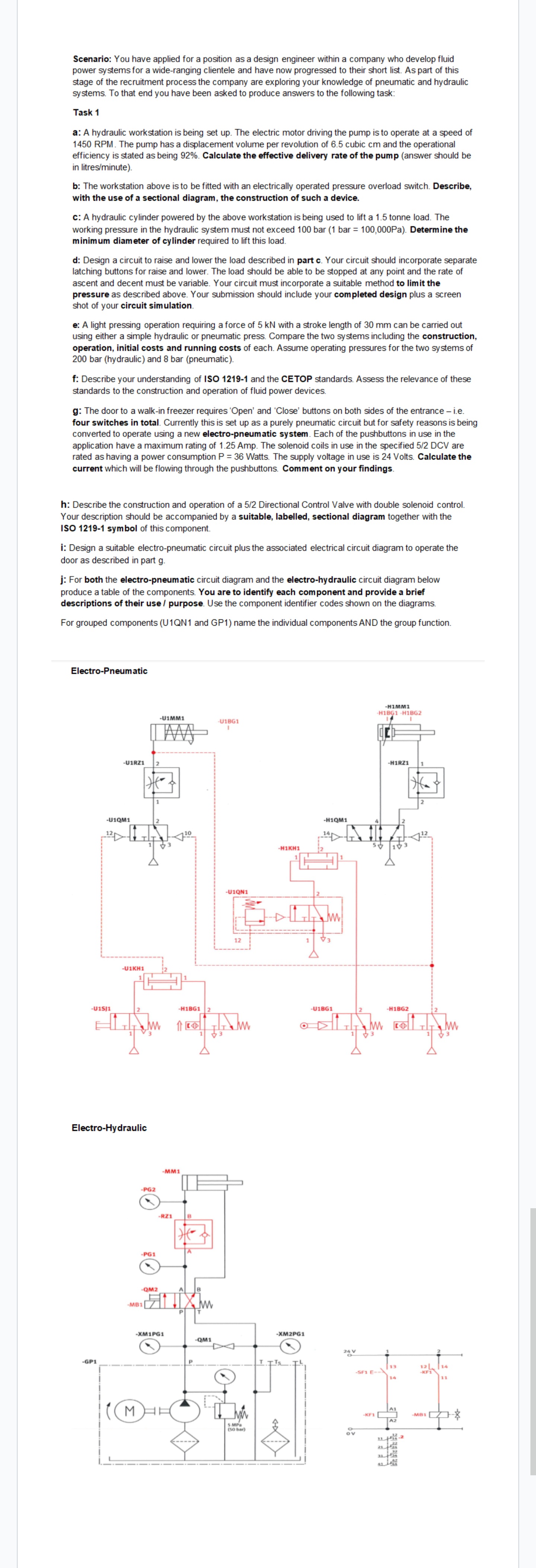
Scenario: You have applied for a position as a design engineer within a company who develop fluid power systems for a wide-ranging clientele and have now progressed to their short list. As part of this stage of the recruitment process the company are exploring your knowledge of pneumatic and hydraulic systems. To that end you have been asked to produce answers to the following task: Task 1 a: A hydraulic workstation is being set up. The electric motor driving the pump is to operate at a speed of 1450 RPM. The pump has a displacement volume per revolution of 6.5 cubic cm and the operational efficiency is stated as being 92%. Calculate the effective delivery rate of the pump (answer should be in litres/minute). b: The workstation above is to be fitted with an electrically operated pressure overload switch. Describe, with the use of a sectional diagram, the construction of such a device. c: A hydraulic cylinder powered by the above workstation is being used to lift a 1.5 tonne load. The working pressure in the hydraulic system must not exceed 100 bar (1 bar = 100,000Pa). Determine the minimum diameter of cylinder required to lift this load. d: Design a circuit to raise and lower the load described in part c. Your circuit should incorporate separate latching buttons for raise and lower. The load should be able to be stopped at any point and the rate of ascent and decent must be variable. Your circuit must incorporate a suitable method to limit the pressure as described above. Your submission should include your completed design plus a screen shot of your circuit simulation. e: A light pressing operation requiring a force of 5 kN with a stroke length of 30 mm can be carried out using either a simple hydraulic or pneumatic press. Compare the two systems including the construction, operation, initial costs and running costs of each. Assume operating pressures for the two systems of 200 bar (hydraulic) and 8 bar (pneumatic). f: Describe your understanding of ISO 1219-1 and the CETOP standards. Assess the relevance of these standards to the construction and operation of fluid power devices. g: The door to a walk-in freezer requires 'Open' and 'Close' buttons on both sides of the entrance - i.e. four switches in total. Currently this is set up as a purely pneumatic circuit but for safety reasons is being converted to operate using a new electro-pneumatic system. Each of the pushbuttons in use in the application have a maximum rating of 1.25 Amp. The solenoid coils in use in the specified 5/2 DCV are rated as having a power consumption P = 36 Watts. The supply voltage in use is 24 Volts. Calculate the current which will be flowing through the pushbuttons. Comment on your findings. h: Describe the construction and operation of a 5/2 Directional Control Valve with double solenoid control. Your description should be accompanied by a suitable, labelled, sectional diagram together with the ISO 1219-1 symbol of this component. i: Design a suitable electro-pneumatic circuit plus the associated electrical circuit diagram to operate the door as described in part g. j: For both the electro-pneumatic circuit diagram and the electro-hydraulic circuit diagram below produce a table of the components. You are to identify each component and provide a brief descriptions of their use / purpose. Use the component identifier codes shown on the diagrams. For grouped components (U1QN1 and GP1) name the individual components AND the group function. Electro-Pneumatic -U1RZ1 2 -U1QM1 2 -U1KH1 -U1SJ1 2 Electro-Hydraulic -GP1 -PG2 -HIMMI H1BG1 H1BG2 -U1MM1 -U1BG1 -H1BG1 1 -MM1 -RZ1 B * -PG1 -QM2 A B -MB1 M -XM1PG1 P T -U1QN1 12 -H1KH1 -H1QM1 4 -H1RZ1 1 13 2 -U1BG1 2 -H1BG2 www -QM1 T -XM2PG1 24 V 5 MPa (50 bar) ov 13 12 14 -SF1 E-- -KF1 14 11 A1 -KF1 -MB1 2129 3134 32 41
Step by Step Solution
There are 3 Steps involved in it

Get step-by-step solutions from verified subject matter experts