

Question: Sine wave VG = 3 V (rms) f = 3 kHz Wavegen 1 Analog Discovery 2 Analog Discovery 2 Orange wire Yellow wire Fly-wire
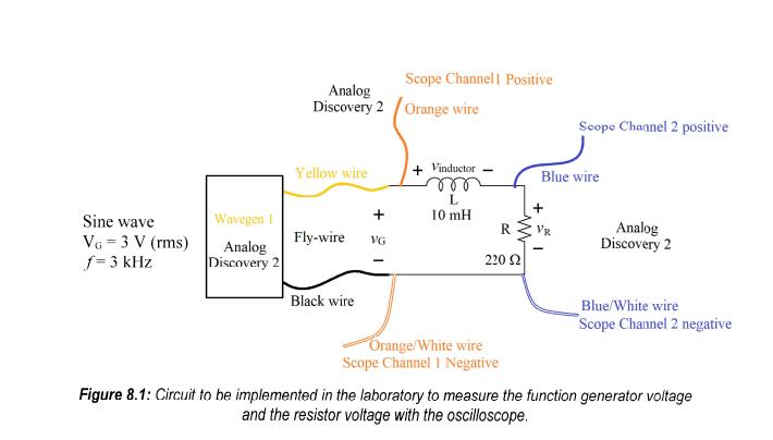
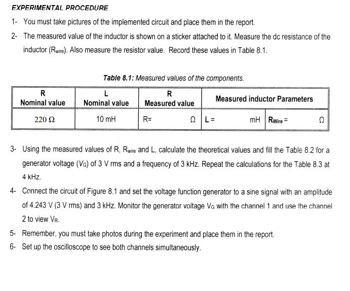
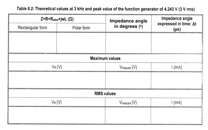
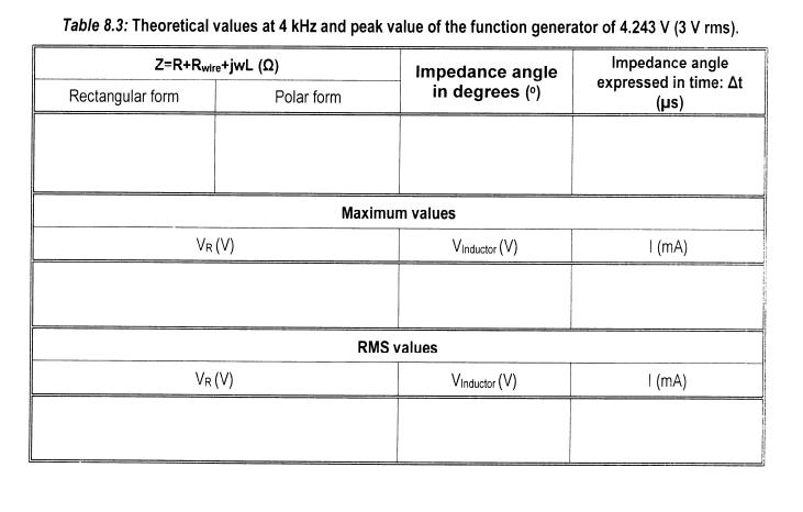
Sine wave VG = 3 V (rms) f = 3 kHz Wavegen 1 Analog Discovery 2 Analog Discovery 2 Orange wire Yellow wire Fly-wire VG Scope Channel I Positive Black wire + Vinductor ror L 10 mH R 220 22 Orange/White wire Scope Channel 1 Negative Scope Channel 2 positive Blue wire + Analog Discovery 2 Blue/White wire Scope Channel 2 negative Figure 8.1: Circuit to be implemented in the laboratory to measure the function generator voltage and the resistor voltage with the oscilloscope. EXPERIMENTAL PROCEDURE 1- You must take pictures of the implemented circuit and place them in the report. 2- The measured value of the inductor is shown on a sticker attached to it. Measure the dc resistance of the inductor (Rwire). Also measure the resistor value. Record these values in Table 8.1. R Nominal value 220 Table 8.1: Measured values of the components. R Measured value L Nominal value 10 mH R= Q|L= Measured inductor Parameters mH Rwire = 22 3- Using the measured values of R, Rwire and L, calculate the theoretical values and fill the Table 8.2 for a generator voltage (VG) of 3 V rms and a frequency of 3 kHz. Repeat the calculations for the Table 8.3 at 4 kHz. 4- Connect the circuit of Figure 8.1 and set the voltage function generator to a sine signal with an amplitude of 4.243 V (3 V rms) and 3 kHz. Monitor the generator voltage VG with the channel 1 and use the channel 2 to view VR. 5- Remember, you must take photos during the experiment and place them in the report. 6- Set up the oscilloscope to see both channels simultaneously. Table 8.2: Theoretical values at 3 kHz and peak value of the function generator of 4.243 V (3 V rms) Z=R+Rwire+jWL (2) Impedance angle expressed in time: At (s) Rectangular form VR (V) VR (V) Polar form Impedance angle in degrees () Maximum values RMS values Vinductor (V) Vinductor (V) | (mA) | (mA) Table 8.3: Theoretical values at 4 kHz and peak value of the function generator of 4.243 V (3 V rms). Z=R+Rwire+jWL (2) Impedance angle expressed in time: At (s) Rectangular form VR (V) VR (V) Polar form Impedance angle in degrees () Maximum values RMS values Vinductor (V) Vinductor (V) | (mA) | (mA)
Step by Step Solution
3.35 Rating (164 Votes )
There are 3 Steps involved in it

Get step-by-step solutions from verified subject matter experts