

Question: Sequential Logic Design Overview - Recall that you designed and verified the control logic part of the vending machine controller That is , the combinationsl
Sequential Logic Design
Overview
Recall that you designed and verified the control logic part of the vending machine controller
That is the combinationsl aspect which determines Accept andor Dispense based on the state
In this lab, you will implement the neat state logic of the controller
Your responsibility is to determine the correct next state for each state
Your block design must not be remate refer to lab and must be named wending eachine
You are strongly encouraged to only use a combinstion of NAND, NOR. NOT gates since these are the only logic gates you have ave in your lab lit
Specification
Recall the state definition as follow:
As this is sequential logic, you will use the filpflop module ecelasdff we have provided:
Notice that the reset pin on the flipflop is activelow and ayynchronous. Since the reset is asynchronous, the filpflop resets independent clock. Therefore, we say that this flipflop resets to upan the falling edge of rstn as opposed to the rising edge since the reset is act lowht
You will cambine the design with lab for a complete contraller, the top lavel port is as follaws:
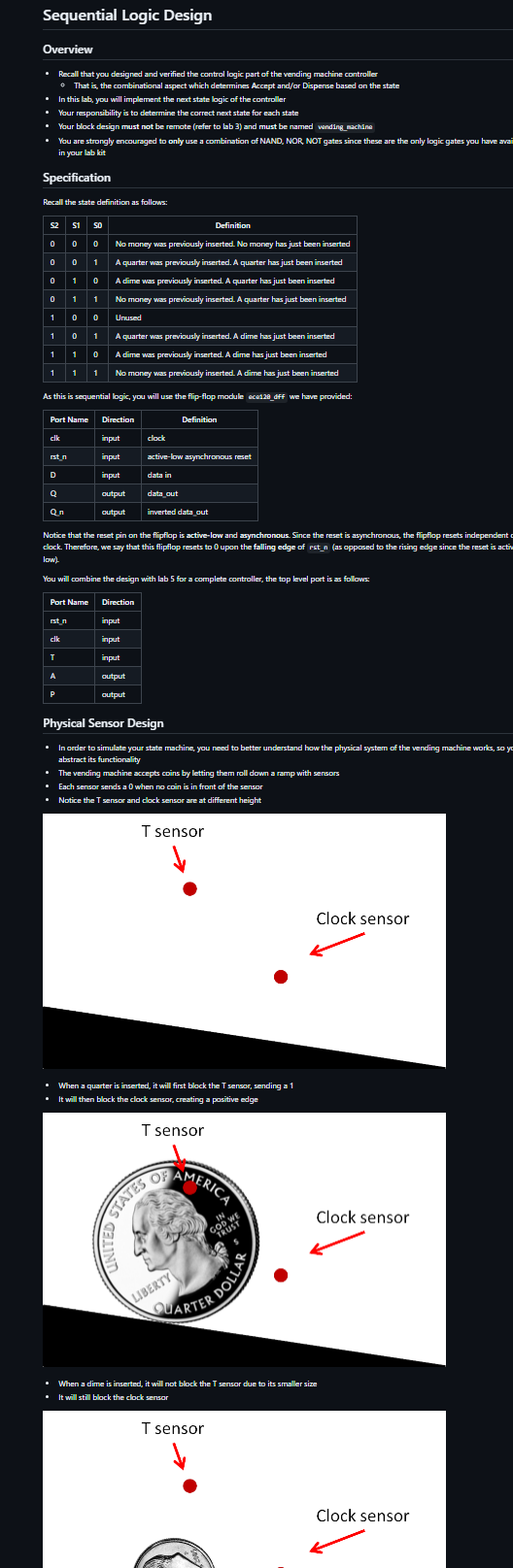
Physical Sensor Design
In order to simulate your state machine, you need to better understand how the physical syatem of the vending machine works, so y abstract its functionality
The vending machine accepts coins by letting them roll down a ramp with sensors
Esch sensar sends a when no coin is in front of the sensar
Notice the T sensor and clock sensor are at different height
When a quarter is inserted, it will first block the T sensos sending a
It will then block the clock sensor creating a pasitive edge
When a dime is inserted, it will not block the T sensor due to its smaller size
It will still block the clock sensor You should then use T as the input for the state transitions:
T when a quarter has been inserted and mathrmT when a dime has been irserted.
This state machine is also driven by a clock that indicates when a coin has been inserted.
Abstraction
Once you come up with neatstate eqpressions for $ and the next step would be to combine the neatstate circuit with the output generation circuit that we built in lab Since lab should be complete and working by now, we can simply treat it as a black bax with inputs $ and and outputs A and P To do this concretely, we will package bb S into an IP and import it into our lab block diagram. This stap is known as abstraction
In order to achieve this, follow these steps:
Open your bb project
Click on Teols rightarrow Cresate and Package Maw IP Mext
Select package a bleck design fron the current project under Packaging Cptiens and hit Mext
It does not matter where you set the IP lacation but you have to remamber it Here is an erample pathc sim haresareebsebfp
Keep dicking on ox and finally Finish
A window called Package IP desige should show up We will keep most of the default settings but let's change the name of our IP so we can essily identify it
Under Identification, change Mere, Bisplay nawe, and Description to wendingsachinecontrollogic
You will also need to archive the IP for grading purpages archive of D
Make sure the check box is ticked
Now simply click on Package ID under Revien and Package.
Congratulations! You have abstracted lab into an IP resiby to be used in lab Now, we can finally begin working on building the nextstate logic and combining it with our mathbbP :
Creste a new project for this lab and import the ECE IPs, just fike you did in labs and
Note: Your wivado project name and block design name must be named wending reachine, failure to do so will result in a
Now go to Tools rightarrow Settings... Repesitory under IP
Click the button and lock for your IP Vivado should detect that IP has been added.
Hit ok rightarrow Apply rightarrow ok and creste a new block disgram named wending eachine
Now try to add your IP just as you would for a gate. If you were successful, you should see the following component show up
Example Waveform
Remember to reset the controller to the initial state
A quarter was inserted at time
cik raised at time
Coin is accepted
Product is not dispensed
Anather quarter was inserted at time
ck raised at time
Coin is not accepted
Product is not dispensed
A dime was inserted at time
cik raised at time
Coin is accepted
Product is dispensed
Verification
We have provided an empty testbench for you
You will simulbte the insertion of the coins using the tasts we have provided
You will then verify the output using assortap
Here is an example for the waveform above:
initial begin
intt;
reset;
quarter;
qustertap:
qarter;
assertapa
assertAP
Step by Step Solution
There are 3 Steps involved in it
1 Expert Approved Answer
Step: 1 Unlock

Question Has Been Solved by an Expert!
Get step-by-step solutions from verified subject matter experts
Step: 2 Unlock
Step: 3 Unlock