

Question: Solution: The given sequential logic diagram A buffer component is used at input of A flip flop The state equations are D A = Q
Solution:
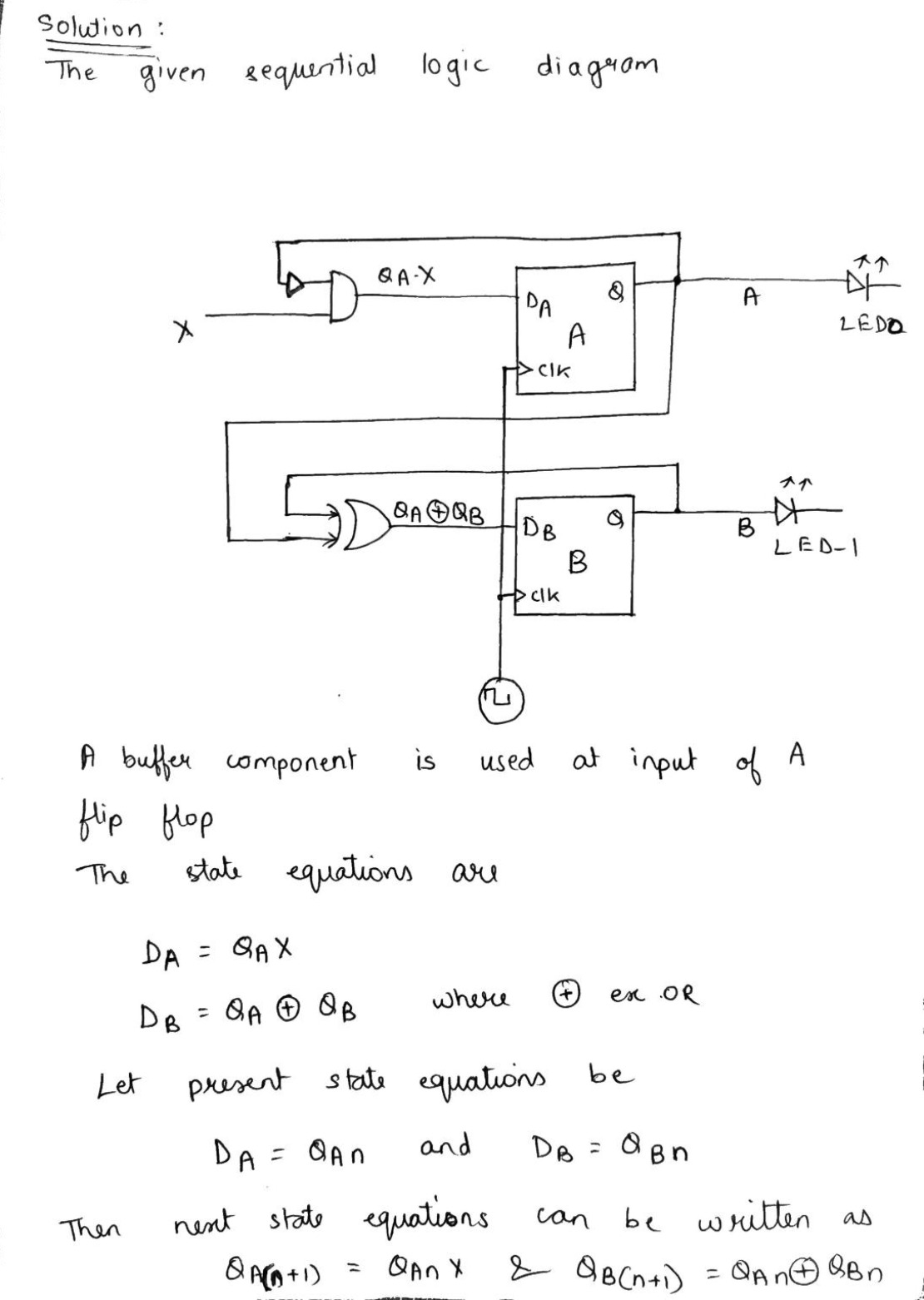
The given sequential logic diagram
A buffer component is used at input of
flip flop
The state equations are
where
Let present state equations be
and
Then next state equations can be written as
&
Step by Step Solution
There are 3 Steps involved in it
1 Expert Approved Answer
Step: 1 Unlock

Question Has Been Solved by an Expert!
Get step-by-step solutions from verified subject matter experts
Step: 2 Unlock
Step: 3 Unlock