

Question: Task 2 The structure below (figure 1) showed a beam and column house of parking garage. This is a Steel structure which includes a
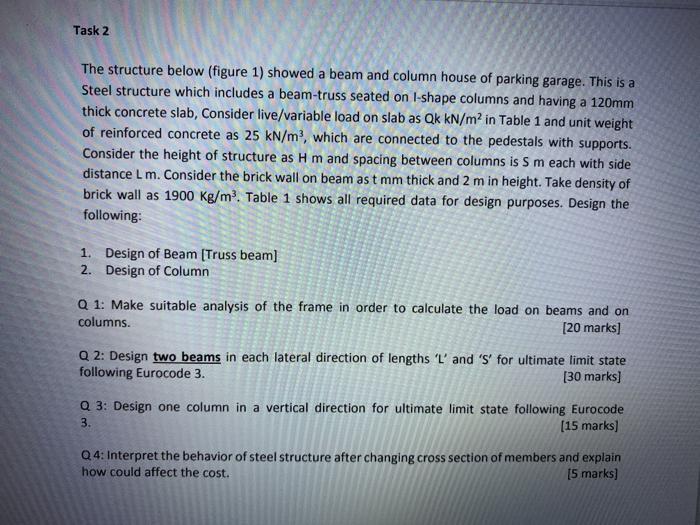
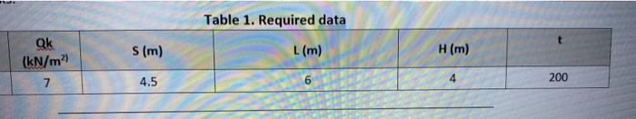
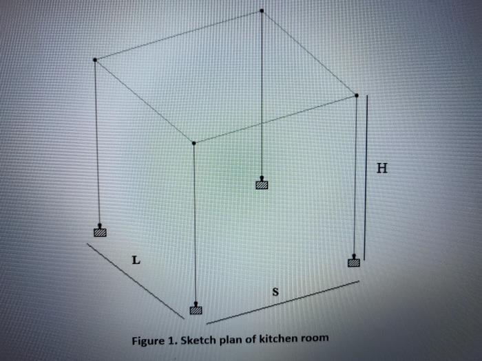
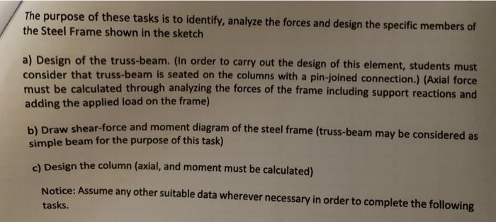
Task 2 The structure below (figure 1) showed a beam and column house of parking garage. This is a Steel structure which includes a beam-truss seated on I-shape columns and having a 120mm thick concrete slab, Consider live/variable load on slab as Qk kN/m in Table 1 and unit weight of reinforced concrete as 25 kN/m, which are connected to the pedestals with supports. Consider the height of structure as H m and spacing between columns is S m each with side distance L m. Consider the brick wall on beam as t mm thick and 2 m in height. Take density of brick wall as 1900 Kg/m. Table 1 shows all required data for design purposes. Design the following: 1. Design of Beam [Truss beam] 2. Design of Column Q 1: Make suitable analysis of the frame in order to calculate the load on beams and on columns. [20 marks] Q 2: Design two beams in each lateral direction of lengths 'L' and 'S' for ultimate limit state following Eurocode 3. [30 marks] Q 3: Design one column in a vertical direction for ultimate limit state following Eurocode 3. [15 marks] Q4: Interpret the behavior of steel structure after changing cross section of members and explain how could affect the cost. [5 marks] nare Qk (kN/m) 7 S (m) 4.5 Table 1. Required data L (m) 6 H (m) 4 200 L W S Figure 1. Sketch plan of kitchen room H The purpose of these tasks is to identify, analyze the forces and design the specific members of the Steel Frame shown in the sketch a) Design of the truss-beam. (In order to carry out the design of this element, students must consider that truss-beam is seated on the columns with a pin-joined connection.) (Axial force must be calculated through analyzing the forces of the frame including support reactions and adding the applied load on the frame) b) Draw shear-force and moment diagram of the steel frame (truss-beam may be considered as simple beam for the purpose of this task) c) Design the column (axial, and moment must be calculated) Notice: Assume any other suitable data wherever necessary in order to complete the following tasks. i
Step by Step Solution
3.35 Rating (164 Votes )
There are 3 Steps involved in it

Get step-by-step solutions from verified subject matter experts