

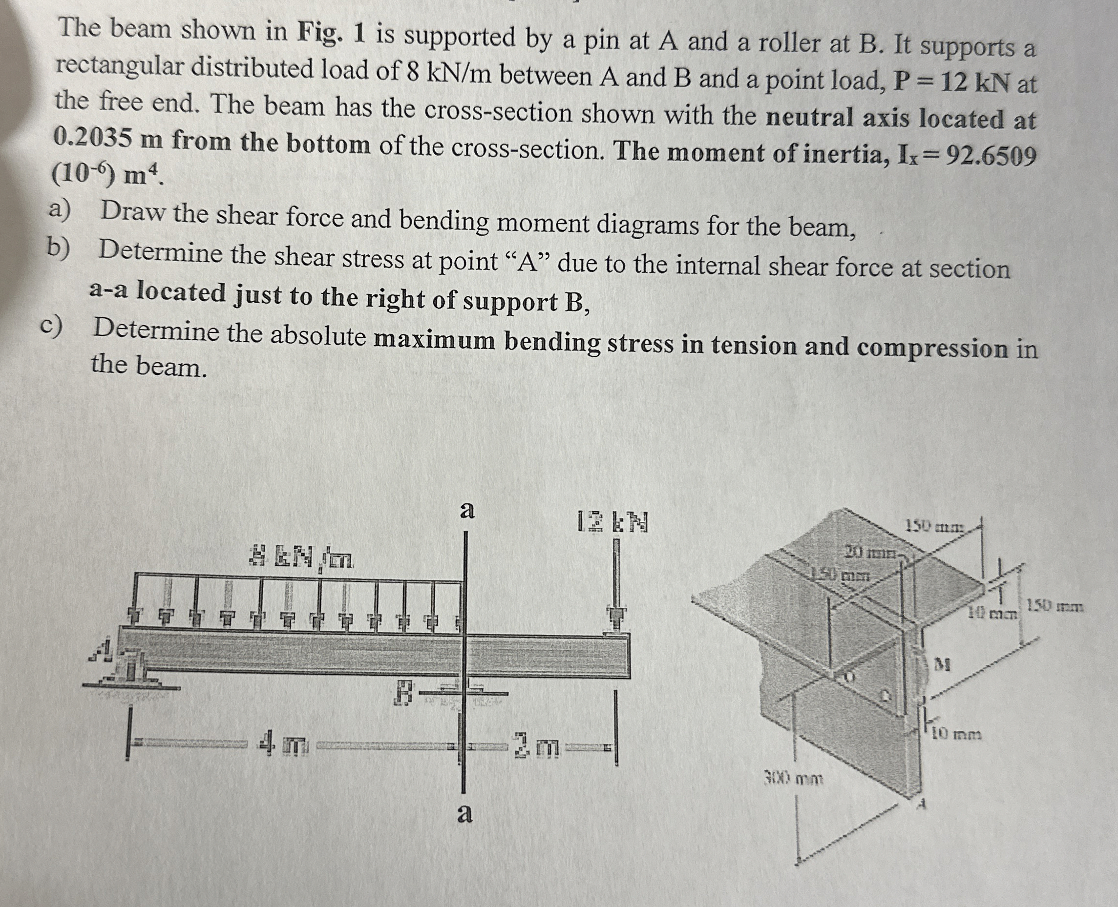
Question: The beam shown in Fig. 1 is supported by a pin at A and a roller at B . It supports a rectangular distributed load
The beam shown in Fig. is supported by a pin at A and a roller at B It supports a rectangular distributed load of between A and and a point load, at the free end. The beam has the crosssection shown with the neutral axis located at m from the bottom of the crosssection. The moment of inertia,
a Draw the shear force and bending moment diagrams for the beam,
b Determine the shear stress at point due to the internal shear force at section aa located just to the right of support
c Determine the absolute maximum bending stress in tension and compression in the beam.
Step by Step Solution
There are 3 Steps involved in it
1 Expert Approved Answer
Step: 1 Unlock

Question Has Been Solved by an Expert!
Get step-by-step solutions from verified subject matter experts
Step: 2 Unlock
Step: 3 Unlock