

Question: The beam shown in Figure 2 has a hinge support at A and the supports B, C and D are rollers. It carries downward
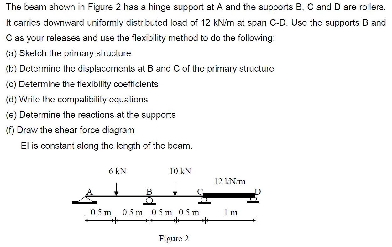
The beam shown in Figure 2 has a hinge support at A and the supports B, C and D are rollers. It carries downward uniformly distributed load of 12 kN/m at span C-D. Use the supports B and C as your releases and use the flexibility method to do the following: (a) Sketch the primary structure (b) Determine the displacements at B and C of the primary structure (c) Determine the flexibility coefficients (d) Write the compatibility equations (e) Determine the reactions at the supports (f) Draw the shear force diagram El is constant along the length of the beam. 6 kN 10 kN 12 kN/m A B 0.5 m 0.5 m 0.5 m 0.5 m 1 m Figure 2
Step by Step Solution
3.40 Rating (147 Votes )
There are 3 Steps involved in it

Get step-by-step solutions from verified subject matter experts