

Question: The black lines represent a U - shaped rigid structure. The structure is attached to the wall by a frictionless pinioint at point A .
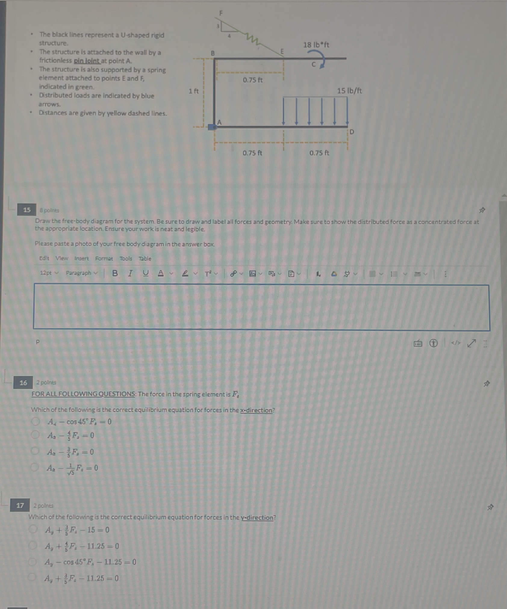
The black lines represent a shaped rigid structure.
The structure is attached to the wall by a frictionless pinioint at point
The structure is also supported by a spring element attached to points E and F indicated in green.
Distributed loads are indicated by blue arrows.
Distances are given by yellow dashed lines.
polints
Draw the freebody diagram for the system. Be sure to draw and label all forces and geometry. Make sure to show the distributed force as a concentrated force at the appropriate location. Ensure your work is neat and legible.
Please paste a photo of your free body diagram in the answer box:
Edit Vlew insert Format Tools Table
pt
Faragraph
polints
FOR AIL FOLLOWING QUESTIONS: The force in the spring element is
Which of the following is the correct equilibrium equation for forces in the x direction?
points
Which of the following is the correct equilibrium equation for forces in the direction?
Step by Step Solution
There are 3 Steps involved in it
1 Expert Approved Answer
Step: 1 Unlock

Question Has Been Solved by an Expert!
Get step-by-step solutions from verified subject matter experts
Step: 2 Unlock
Step: 3 Unlock