

The circuit in Figure P28.61 contains two resistors, R1 5 2.00 kV and R2 5 3.00 kV,
Fantastic news! We've Found the answer you've been seeking!
Question:
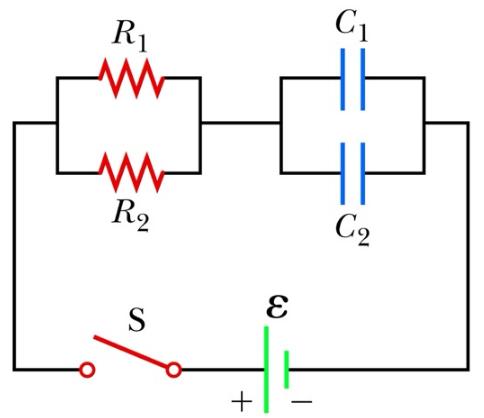
The circuit in Figure P28.61 contains two resistors, R1 5 2.00 kV and R2 5 3.00 kV, and two capacitors, C1 5 2.00 mF and C2 5 3.00 mF, connected to a battery with emf e 5 120 V. If there are no charges on the capacitors before switch S is closed, determine the charges on capacitors (a) C1 and (b) C2 as functions of time, after the switch is closed.
Expert Answer:
The equivalent resistance R1and R2 are connected in parallel of curcuitReqR1R2 R1R2R1R2235kilooh... View the full answer

Related Book For 

College Physics
ISBN: 978-0495113690
7th Edition
Authors: Raymond A. Serway, Jerry S. Faughn, Chris Vuille, Charles A. Bennett
Posted Date:
