

Question: The figure below shows a 16-bit carry-bypass adder. The inputs are denoted as (A 15 A 14 A 0 ) and (B 15 B 14
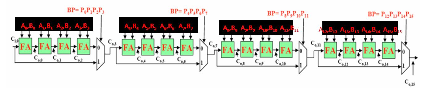
The figure below shows a 16-bit carry-bypass adder. The inputs are denoted as (A15A14…A0) and (B15B14…B0), where A15 and B15 are the MSBs. Pi and Gi follow the definitions in the lecture (i.e., Pi=Ai xor Bi, Gi=Ai & Bi). Outputs Si are omitted for simplicity. Please note that independent calculations can be performed concurrently in hardware (e.g., all Pi’s and Gi’s can be calculated simultaneously).
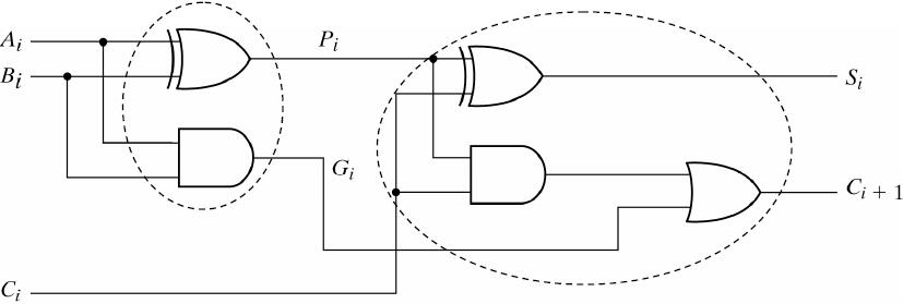
The following figure shows the detail inside each full adder based on P and G.
 |
BP= P.PP:P, AB A,B A,B A, B FA FA FA Co2 BP= PPP&P, AB AB AB A, B FARFA FA FA Cos C06 Cot BP= P&P,P10P11 AB A,B, A1B10 ALB11 FARFARFARFA Co Co.10 BP= P1:P13P14 P15 AB12 A1B13 AB4 A15B15 Coll FARFARFARFA Coll Co,13 Coll 0,15
Step by Step Solution
There are 3 Steps involved in it
Inputs The adder takes two 16bit binary numbers A and B as inputs Each bit is labeled from A15 most significant bit to A0 least significant bit for A ... View full answer

Get step-by-step solutions from verified subject matter experts