

Question: The floor - beam - column system shown in Fig. 2 is subjected to a superimposed D L = 4 5 p s f (
The floorbeamcolumn system shown in Fig. is subjected to a superimposed excluding the selfwt of the floor slab an superimposed ABCD portion of the slab is cantilevered from the support beam AB The MNBA portion of the slab is supported beams MN and AB built integrally on two sides. Design the slabfloor system MNBCDA. Use Ultimate Strength Design method USD all possible live load reductions. Given: Use ACI defined moment coefficients.
a Design the whole slabsystem MNBCDA for flexure and shear. points
b Show all possible reinforcing details cross sectional profile & plan view for reinforcing lay out points
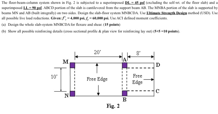
The floorbeamcolumn system shown in Fig. is subjected to a superimposed DL psf excluding the selfwt of the floor slab and a superimposed ABCD portion of the slab is cantilevered from the support beam The MNBA portion of the slab is supported by beams and built integrally on two sides. Design the slabfloor system MNBCDA. Use Ultimate Strength Design method USD Use all possible live load reductions. Given: Use ACI defined moment coefficients.
a Design the whole slabsystem MNBCDA for flexure and shear. points
b Show all possible reinforcing details cross sectional profile & plan view for reinforcing lay out points
Fig.
Step by Step Solution
There are 3 Steps involved in it
1 Expert Approved Answer
Step: 1 Unlock

Question Has Been Solved by an Expert!
Get step-by-step solutions from verified subject matter experts
Step: 2 Unlock
Step: 3 Unlock