

Question: The following figure shows a test setup for determining the energy loss through a heat exchanger. Water at x C flows upward at y m?/s
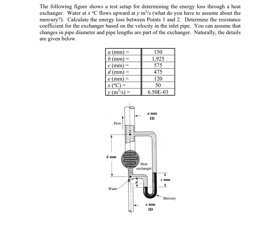
The following figure shows a test setup for determining the energy loss through a heat exchanger. Water at x C flows upward at y m?/s (what do you have to assume about the mercury?). Calculate the energy loss between Points 1 and 2. Determine the resistance coefficient for the exchanger based on the velocity in the inlet pipe. You can assume that changes in pipe diameter and pipe lengths are part of the exchanger. Naturally, the details are given below. a (mm) = b (mm) = c (mm) = d (mm) = e (mm) = x (C) = ly (m/s) = 150 1,925 575 475 120 50 6.50E-03 a mm ID Flow b mm Heat exchanger cmm Water Mercury e mm ID
Step by Step Solution
There are 3 Steps involved in it
1 Expert Approved Answer
Step: 1 Unlock

Question Has Been Solved by an Expert!
Get step-by-step solutions from verified subject matter experts
Step: 2 Unlock
Step: 3 Unlock