

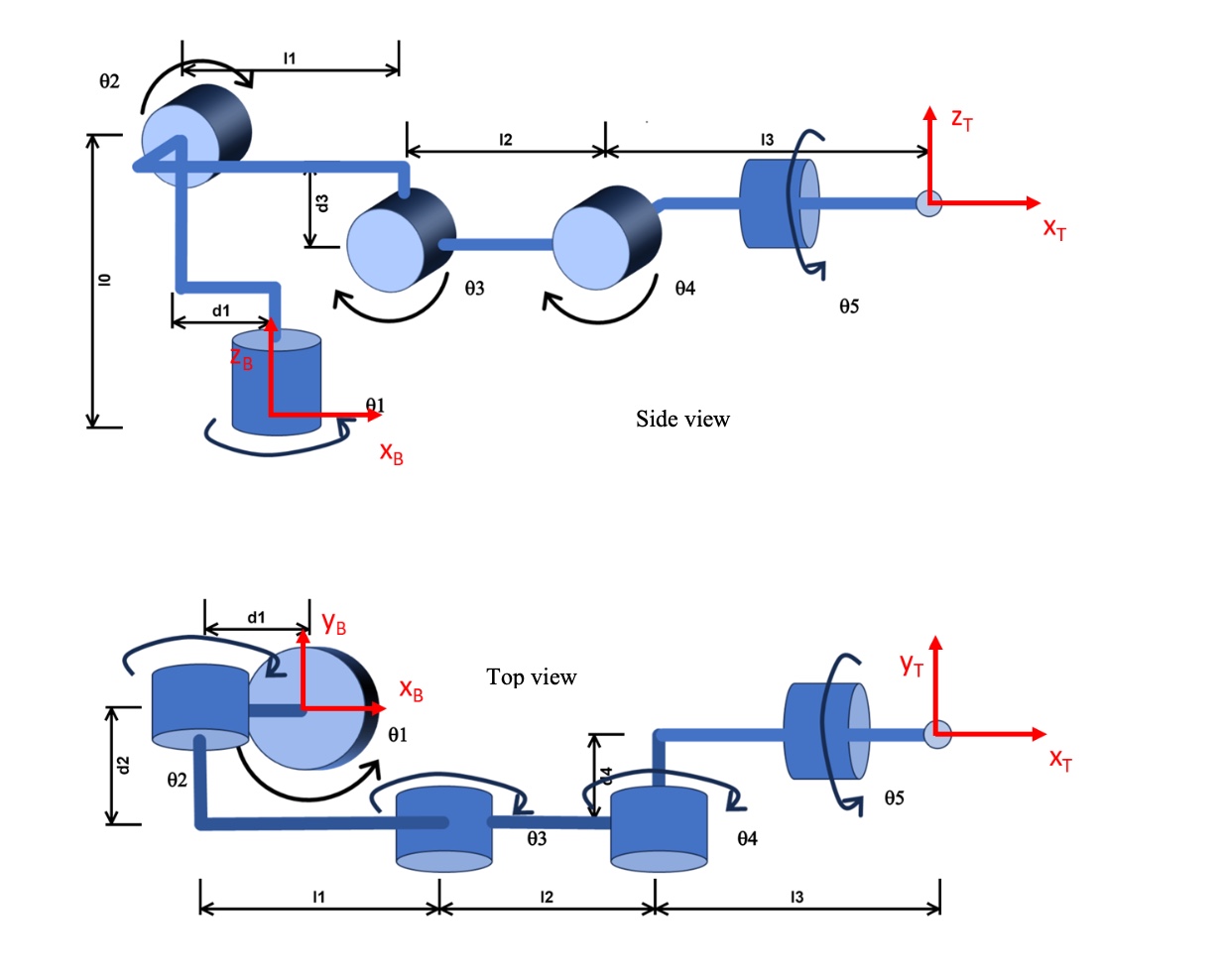
Question: The link length are defined as follows: l 0 = 0 . 3 5 m l 1 = 0 . 2 5 m l 2
The link length are defined as follows:
There are displacements between some of the joints:
The picture above shows the robot in the configuration where all joint angles are The direction of
positive rotation is shown about each joint.
The simulator will actually show one additional joint joint corresponding to the opening of the gripper.
This, however, is not relevant for the kinematic functions and can be ignored.
Determine and implement the inverse kinematic function for this Robot. Points
Derivation points
You are to derive and implement a partial inverse kinematic solution for the robot manipulator. To make
this problem tractable, we assume and require that the X axis of the tool frame is pointed straight
down ie hat is parallel to hat Turn in a handwritten and scanned or typed solution.
HINT: To determine this inverse kinematics you should decompose the problem. Draw the system from
above and from the side for angles other than I recommend an "elbow up configuration. You
can determine without considering the other joints using trigonometry. Simplify solving for
by first moving up the wrist frame ie to where is in my FK solution. Attached are hints and the figure.
Step by Step Solution
There are 3 Steps involved in it
1 Expert Approved Answer
Step: 1 Unlock

Question Has Been Solved by an Expert!
Get step-by-step solutions from verified subject matter experts
Step: 2 Unlock
Step: 3 Unlock