

Question: The Robot In the first examples you are to determine the forward kinematics for the following 5 degree - offreedom robot manipulator. A drawing is
The Robot
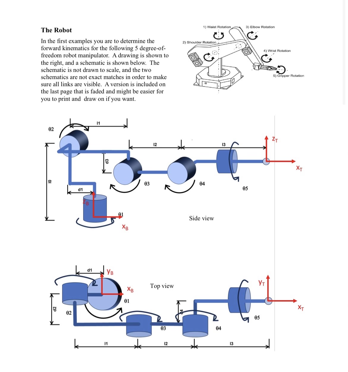
In the first examples you are to determine the forward kinematics for the following degreeoffreedom robot manipulator. A drawing is shown to the right, and a schematic is shown below. The schematic is not drawn to scale, and the two schematics are not exact matches in order to make sure all links are visible. A version is included on the last page that is faded and might be easier for you to print and draw on if you want. The link length are defined as follows:
There are displacements between some of the joints:
The picture above shows the robot in the configuration where all joint angles are The direction of
positive rotation is shown about each joint.
The simulator will actually show one additional joint joint corresponding to the opening of the gripper.
This, however, is not relevant for the kinematic functions and can be ignored.
Determine and implement the forward kinematic function for this Robot. Points
You need to determine the transformation from configuration space joint angles to the Cartesian location
of the tool frame in base frame coordinates using the DH convention and parameters.
Derivation points
a Determine the DH parameters for each jointlink Provide a table of all DH parameters. Feel free
to print out and use the figure above to show your axes, etc.
b Provide the transform matrices for each link
Step by Step Solution
There are 3 Steps involved in it
1 Expert Approved Answer
Step: 1 Unlock

Question Has Been Solved by an Expert!
Get step-by-step solutions from verified subject matter experts
Step: 2 Unlock
Step: 3 Unlock