

Question: The phase-controlled 6-pulse (3-phase) rectifier, shown in Fig. PI.I, is supplied from a 460-V, 60-Hz power line, whose inductance, L,, is seen from the
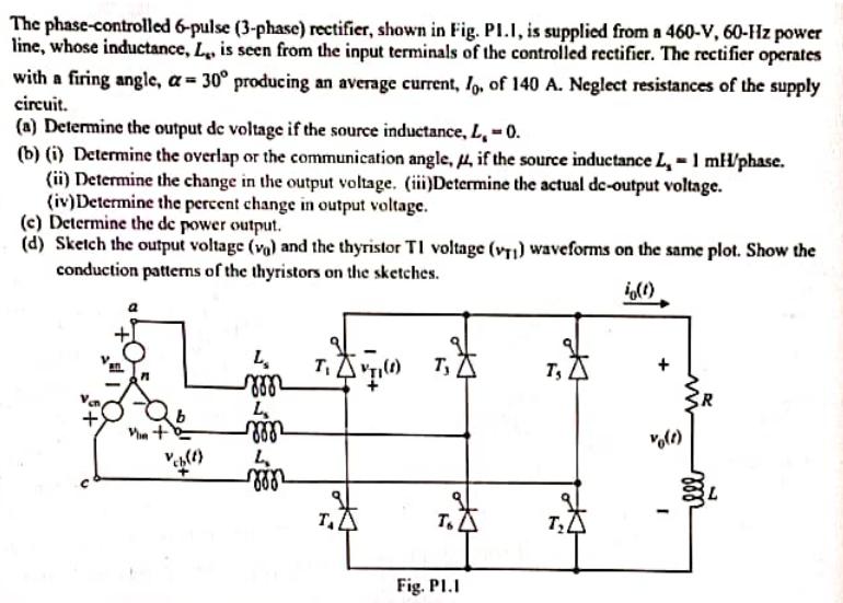
The phase-controlled 6-pulse (3-phase) rectifier, shown in Fig. PI.I, is supplied from a 460-V, 60-Hz power line, whose inductance, L,, is seen from the input terminals of the controlled rectifier. The rectifier operates with a firing angle, a= 30 producing an average current, Io. of 140 A. Neglect resistances of the supply circuit. (a) Determine the output de voltage if the source inductance, L, -0. (b) (i) Determine the overlap or the communication angle, , if the source inductance L = 1 mH/phase. (ii) Determine the change in the output voltage. (iii)Determine the actual de-output voltage. (iv)Determine the percent change in output voltage. (e) Determine the de power output. (d) Sketch the output voltage (va) and the thyristor TI voltage (VT) waveforms on the same plot. Show the conduction patterns of the thyristors on the sketches. 40(1) Vin + Vch(t) L m L mm L zon T 71 (0) T To Fig. Pl.I TSA TA I illl
Step by Step Solution
3.47 Rating (160 Votes )
There are 3 Steps involved in it
The detailed ... View full answer

Get step-by-step solutions from verified subject matter experts