

Question: The project is to design a PI controller to control the position of a shaft of an electromechanical system that has the following transfer
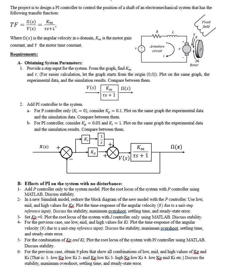
The project is to design a PI controller to control the position of a shaft of an electromechanical system that has the following transfer function: TF = n (s) V(s) = Km TS+1' Where (s) is the angular velocity in s-domain, K is the motor gain constant, and T the motor time constant. Requirements: X(s) + Km TS + 1 Kp R Armature circuit A- Obtaining System Parameters: 1. Provide a step input for the system. From the graph, find Km and T. (For easier calculation, let the graph starts from the origin (0,0)). Plot on the same graph, the experimental data, and the simulation results. Compare between them. V(s) n(s) V(s) L 2. Add PI controller to the system. a- For P controller only (K; = 0), consider K = 0.1. Plot on the same graph the experimental data and the simulation data. Compare between them. b- For PI controller, consider K = 0.05 and K = 1. Plot on the same graph the experimental data and the simulation results. Compare between them. K Km TS + 1 be Rotor Fixed field n(s) B- Effects of PI on the system with no disturbance: 1- Add P controller only to the system model. Plot the root locus of the system with P controller using MATLAB. Discuss stability. 2- In a new Simulink model, redraw the block diagram of the new model with the P controller. Use low, mid, and high values for Kp. Plot the time-response of the angular velocity (0) due to a unit-step reference input). Discuss the stability, maximum overshoot, settling time, and steady-state error. 3- Set Kp =0. Plot the root locus of the system with I controller only using MATLAB. Discuss stability. 4- For the previous case, use low, mid, and high values for Ki. Plot the time-response of the angular velocity (8) due to a unit-step reference input). Discuss the stability, maximum overshoot, settling time, and steady-state error. 5- For the combination of Kp and Ki, Plot the root locus of the system with PI controller using MATLAB. Discuss stability. 6- For the previous case, obtain 9 plots that show all combinations of low, mid, and high values of Kp and Ki (That is: 1- low Kp low Ki 2- mid Kp low Ki 3-high Kp low Ki 4- low Kp mid Ki etc.) Discuss the stability, maximum overshoot, settling time, and steady-state error.
Step by Step Solution
3.45 Rating (158 Votes )
There are 3 Steps involved in it
To tackle this project youll need to follow these steps A Obtaining System Parameters 1 Perform a st... View full answer

Get step-by-step solutions from verified subject matter experts