

Question: The single- cycle computer in Figure 8-15 executes the five instructions described by the register transfers in the table that follows. (a) Complete the following
The single- cycle computer in Figure 8-15 executes the five instructions described by the register transfers in the table that follows.
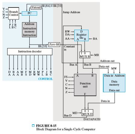
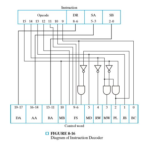
(a) Complete the following table, giving the binary instruction decoder outputs from Figure 8-16 during execution of each of the instructions:
| Instruction Register Transfer | DA | AA | BA | BA | FS | MD | RW | MW | PL | JB |
| R[0] R[7] R[3] | ||||||||||
| R[1] M[R[4]] | ||||||||||
| R[2] R[5]+2 | ||||||||||
| R[3] sl R[6] | ||||||||||
| if (R([4] = 0) PC PC+se AD else PC PC+1 |
(b) Complete the following table, giving the instruction in binary for the single- cycle computer that executes the register transfer (if any field is not used, give it the value 0):
| Instruction Register Transfer | Opcode | DR | SA | SB or Operand |
| R[0] R[7]+R[6] | ||||
| R[1] R[5]-1 | ||||
| R[2] sl R[4] | ||||
| R[3] R[3] | ||||
| R[4] R[2]vR[1] |
Extend C Branch N-Control Jump Address RW DA| Register AA A file B-BA Instruction Zero fill Constant Instruction decoder Address out Bus I Data out Mw DBAM F M R M PJ B A A A B S D W W L B C FS Data unit Data out Data in MD- MUXD Bus D DATAPATH FIGURE8-15 Block Diagram for a Single-Cycle Computer
Step by Step Solution
There are 3 Steps involved in it

Get step-by-step solutions from verified subject matter experts