

Question: This assignment covers the sequential circuit component: Register and ALU. In this as- signment you are supposed to create your own storage component for
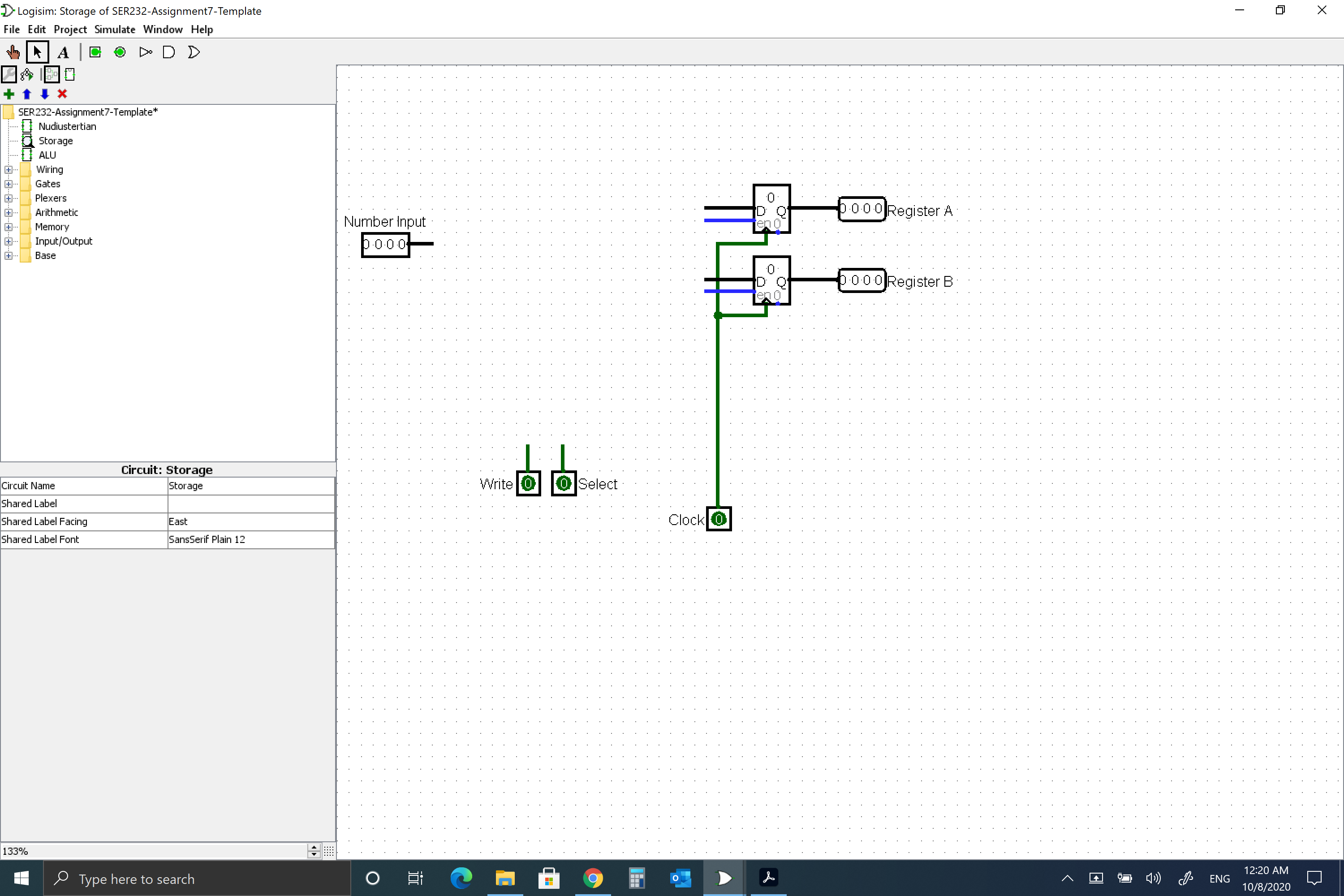
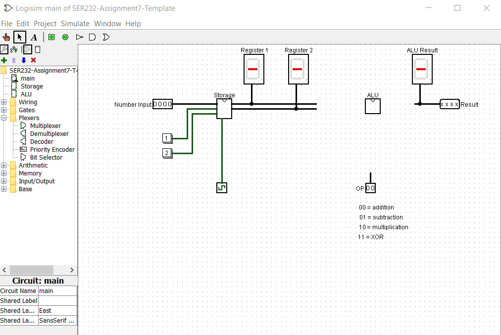
This assignment covers the sequential circuit component: Register and ALU. In this as- signment you are supposed to create your own storage component for two numbers using registers. Those two numbers are then passed into a custom ALU that calculates the result of one of four possible operations. Key aspect of this assignment is to understand how to control registers, how to route signals and how to design a custom ALU. Tasks Use the provided template to implement your storage component and custom ALU. Storage The storage component must function as follows: Changing the value of Number Input is not allowed to have any effect on the register outputs of the storage component (e.g. visible on hex display in main). . Only pressing the Write button is allowed to have an effect on the outputs of the storage component and is supposed to store the current input value into the selected register. The Register Select input will determine which register is being written to. If the select value is 0, the value will be stored in register 1. If the value is 1, register 2 will be used. In order to route the input value to the correct register, you must use a demulti- plexer. Use the enable input of the demultiplexer to trigger the writing. Note: The non-selected outputs of the demultiplexer will always output 0. To prevent storing this value in the other register, which is currently not being written to, use the enable input of the registers to make sure only the correct register stores the value. If the register enable is 1, it will store with every rising edge of the clock. If 0, it will ignore all rising edges from the clock and keep its current value. Remember that the register select indicates which register is supposed to store the value. The two outputs (Register 1 and Register 2) will always show the value that is currently stored in the respective register. Important: Always make sure the Logisim clock is running before you test anything (Simulate, Ticks Enabled; you can also increase the Tick Frequency to 64 Hz to make the circuit respond faster). Notes: The clear input of the register should not be used (do not connect anything to them). Custom ALU Use the provided subcircuit in the template to implement your ALU. You do not have to create additional subcircuits to do this. The ALU has a total of three inputs: First number, second number and select operation input. And one output: Result. The first and second number are used as input for the operations the ALU performs. The select input decides which operation result will be on the single output of the ALU. The ALU is upposed to calculate: NumberA OPERATION NumberB. Register 1 of the storage contains NumberA and Register 2 contains NumberB. The ALU must be able to compute signals with a 4-bit width. Make sure to add labels to all inputs and outputs. The following operations should be performed for each select input combination (s1s0): 00: Addition . 01: Multiplication 10: Division 11: Logic Bitwise XOR Notes: You can change the inputs bit width / data bits of any gate to more that 1-bit. This will apply the logic operation bitwise. The Logic Bitwise XOR operation can be done with a single XOR gate. You are also allowed to use the built-in arithmetic logic components and multi- plexer provided by Logisim. If the result is larger than 4 bits, it will be truncated (only 4 LSB will be shown). This behavior is intended for this assignment. Also, negative results do not have to be considered. Once you have implemented the ALU circuit, connect the wires in the Nudiustertian circuit properly and test all four operations of your ALU in combination with the storage component. > Logisim: Storage of SER232-Assignment7-Template File Edit Project Simulate Window Help A D D D +. SER232-Assignment7-Template* +... Plexers Nudiustertian Storage ALU Wiring Gates 133% Arithmetic Memory Input/Output Base Circuit Name Shared Label Shared Label Facing Shared Label Font Circuit: Storage Storage East SansSerif Plain 12 Type here to search 4 Number Input b.0.0.0 i Write 0 O Select Clock 0 O ID Q en 0 0.0.0.0 Register A 0.0.0.0 Register B ENG | 12:20 AM 10/8/2020 X > Logisim: main of SER232-Assignment7-Template File Edit Project Simulate Window Help A COD D +* + LLAAN. &190 + Wiring Gates "Flexers Plexers 8- SER232-Assignment7-T main Storage ALU Multiplexer Mul Demultiplexer Decoder PriPriority Encoder Bit Selector Arithmetic Memory Input/Output Base X Circuit: main Circuit Name main Shared Label Shared La... East Shared La... SansSerif ... Number Input 0000 1 2 Storage 45 Register 1 BI Register 2 FI OP00 ALU Result 00 addition 01 subtraction- 10 multiplication 11 XOR xxxx Result
Step by Step Solution
There are 3 Steps involved in it

Get step-by-step solutions from verified subject matter experts