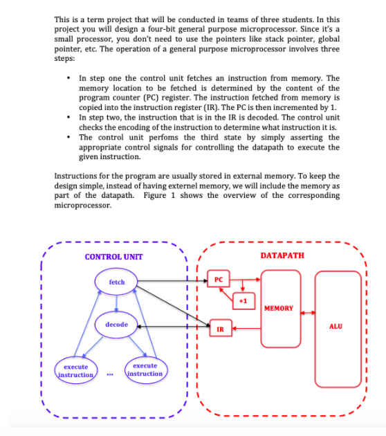
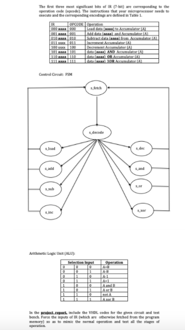
Question: This is a term project that will be conducted in teams of three students. In this project you will design a four-bit general purpose microprocessor.

This is a term project that will be conducted inThis is a term project that will be conducted in

This is a term project that will be conducted in teams of three students. In this project you will design a four-bit general purpose microprocessor. Since it's a small processor, you don't need to use the pointers like stack pointer, global pointer, etc. The operation of a general purpose microprocessor involves three steps: In step one the control unit fetches an instruction from memory. The memory location to be fetched is determined by the content of the program counter (PC) register. The instruction fetched from memory is copied into the instruction register (IR). The PC is then incremented by 1. In step two, the instruction that is in the IR is decoded. The control unit checks the encoding of the instruction to determine what instruction it is. The control unit perfoms the third state by simply asserting the appropriate control signals for controlling the datapath to execute the given instruction. Instructions for the program are usually stored in external memory. To keep the design simple, instead of having externel memory, we will include the memory as part of the datapath. Figure 1 shows the overview of the corresponding microprocessor. CONTROL UNIT DATAPATH fetch PC MEMORY decode ALU IR execute instruction execute instruction - The first three most significant bits of IR 7-bit) are corresponding to the operation code (opcode) The instructions that your microprocessor needs to execute and the corresponding encodings are defined in Table 1. IR OPCODE Operation 000 aaaa 000 Load data (aaaa) to Accumulator (A) 1001 saa001 Add data faaaa) and Accumulator A 010 010 Subtrast data anal from Accumulatori 011011 Increment Accumulator AL 100 x 100 Decrement Accumulator (A) 101 aaaa 101 data saa) AND Accumulator (A) 110 aaaa 110 data (en) OR A A 111 a 111 data (en) XORAL Control Circuit: PSM sfetch s_decode load dec sadid Land sor sor Arithmetic Logic Unit (ALU) Selection Input 10 0 Operation A. 11 o 1 0 10 1 1 1 1 IAS AD A and B A or B not A Axor In the project report include the VHDL codes for the given circuit and test bench Force the inputs of IR (which are otherwise fetched from the program memory) so as to mimic the normal operation and test all the stages of operation This is a term project that will be conducted in teams of three students. In this project you will design a four-bit general purpose microprocessor. Since it's a small processor, you don't need to use the pointers like stack pointer, global pointer, etc. The operation of a general purpose microprocessor involves three steps: In step one the control unit fetches an instruction from memory. The memory location to be fetched is determined by the content of the program counter (PC) register. The instruction fetched from memory is copied into the instruction register (IR). The PC is then incremented by 1. In step two, the instruction that is in the IR is decoded. The control unit checks the encoding of the instruction to determine what instruction it is. The control unit perfoms the third state by simply asserting the appropriate control signals for controlling the datapath to execute the given instruction. Instructions for the program are usually stored in external memory. To keep the design simple, instead of having externel memory, we will include the memory as part of the datapath. Figure 1 shows the overview of the corresponding microprocessor. CONTROL UNIT DATAPATH fetch PC MEMORY decode ALU IR execute instruction execute instruction - The first three most significant bits of IR 7-bit) are corresponding to the operation code (opcode) The instructions that your microprocessor needs to execute and the corresponding encodings are defined in Table 1. IR OPCODE Operation 000 aaaa 000 Load data (aaaa) to Accumulator (A) 1001 saa001 Add data faaaa) and Accumulator A 010 010 Subtrast data anal from Accumulatori 011011 Increment Accumulator AL 100 x 100 Decrement Accumulator (A) 101 aaaa 101 data saa) AND Accumulator (A) 110 aaaa 110 data (en) OR A A 111 a 111 data (en) XORAL Control Circuit: PSM sfetch s_decode load dec sadid Land sor sor Arithmetic Logic Unit (ALU) Selection Input 10 0 Operation A. 11 o 1 0 10 1 1 1 1 IAS AD A and B A or B not A Axor In the project report include the VHDL codes for the given circuit and test bench Force the inputs of IR (which are otherwise fetched from the program memory) so as to mimic the normal operation and test all the stages of operation

Step by Step Solution

There are 3 Steps involved in it

1 Expert Approved Answer
Step: 1 Unlock blur-text-image
Question Has Been Solved by an Expert!

Get step-by-step solutions from verified subject matter experts

Step: 2 Unlock
Step: 3 Unlock

Students Have Also Explored These Related General Management Questions!