

Question: This problem is intended to be solved using Jade simulator. Please show a drawn out circuit diagram ( ex . using and, or , nor,
This problem is intended to be solved using Jade simulator. Please show a drawn out circuit diagram ex using and, or nor, not gates...NOT CODE. Design an adder'subtractor ARITH unit that operates on blt 'two's complement' see the
note in the box below inputs and generates a blt output. It will be useful to generate three
other culput signals to be used by the CMP unit: which is true when the putputs are all zero,
which is true when the addition operation overflows ie the result is top large to be
represented in bits and which is true when the sum is negative ie Overfow
can never occur when the two operands to the addition have different signs; if the two operands
have the same sign, then overfow can be detected if the sign of the result differs from the sign
of the coerands:
Note that this equation uses XB which is the highorder bit of the operand to the adder
itself ie after the XOR gate see the schematic below XA is simply A
Note on "Two's Complement": Our ARITH unit uses 'two's complement' representations of
the binary numbers, in order to be able to represent both posittive and negatve numbers in the
mathematical copations it periorms. In two's complement, the first bit of a binary number lets
you know if the number is positive in which case that first bit is @ or negative in which
case the first bit is In our bit ARITH unit, this first bit is S There are some other
subtleties to how two's complement encodes negative numbers, but those should not affect
your design in this assignment.
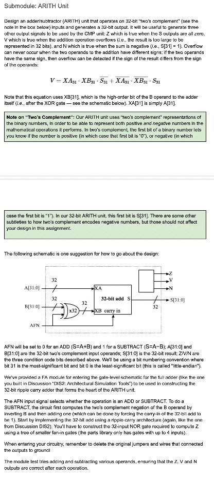
The following schematic is one suggestion for how to about the design:
AFN will be set to for en ADD and for a SUBTRACT ; and
: are the bit two's complement input operands; : is the bit result, are
the three condition code bits described above. We'll be using a bit numbering convention where
bit is the mostsignificant bit and bit is the lesstsignificant bit this is called "littleendian"
We've provided a FA moclule for entering the gatelevel schematic for the full adder lilike the one
you built in Discussion 'DIS: Architectural Simulation Touls' to be used in constructing the
bit ripple carry adder that forms the heart of the ARITH unit.
The AFN input signal selects whether the operation is an ADD or SUBTRACT. To do a
SUBTRACT, the circuit first computes the two's complement negation of the B operand by
inverting and then adding one which can be done by forcing the carryin of the bit add to
be Start by implementing the bit add using a ripplecarry architecture again like the one
from Discussion DIS You'll have to construct the input NOR gate required to compute Z
using a tree of smaller fanin gates the parts library only has gates with up to inputs
When entering your circuitry, remember to delete the original jumpers and wires that connected
the outputs to ground
The module test tries adding and subtracting various operands, ensuring that the and
outputs are correct after each operation.
Step by Step Solution
There are 3 Steps involved in it
1 Expert Approved Answer
Step: 1 Unlock

Question Has Been Solved by an Expert!
Get step-by-step solutions from verified subject matter experts
Step: 2 Unlock
Step: 3 Unlock