

Question: ////////////////////////////////////////////////////////////////////////////////// `timescale 1ns / 1ps //the CPU module from 4.13.4 of the textbook from the online companion material //The initial register and memory state are
////////////////////////////////////////////////////////////////////////////////// `timescale 1ns / 1ps
//the CPU module from 4.13.4 of the textbook from the online companion material //The initial register and memory state are read from .dat files and the //resulting register and memory state are each printed into corresponding .dat //files
module CPU (clock); parameter LW = 6'b100011, SW = 6'b101011, BEQ = 6'b000100, no_op = 32'b0000000_0000000_0000000_0000000, ALUop = 6'b0, BNE = 6'b000101; integer fd,code,str,t; input clock;
reg[31:0] PC, Regs[0:31], IMemory[0:1023], DMemory[0:1023], // separate memories IFIDIR, IDEXA, IDEXB, IDEXIR, EXMEMIR, EXMEMB, // pipeline registers EXMEMALUOut, MEMWBValue, MEMWBIR; // pipeline registers wire [4:0] IDEXrs, IDEXrt, EXMEMrd, MEMWBrd, EXMEMrt, IFIDrs, IFIDrt; //hold register fields wire [5:0] EXMEMop, MEMWBop, IDEXop, IFIDop; //Hold opcodes wire [31:0] Ain, Bin, Cin;
//declare the bypass signals wire takebranch, stall, bypassAfromMEM, bypassAfromALUinWB,bypassBfromMEM, bypassBfromALUinWB, bypassAfromLWinWB, bypassBfromLWinWB; wire bypassIDEXAfromWB, bypassIDEXBfromWB; assign IDEXrs = IDEXIR[25:21]; assign IDEXrt = IDEXIR[20:16]; assign EXMEMrd = EXMEMIR[15:11]; assign EXMEMrt = EXMEMIR[20:16]; assign MEMWBrd = MEMWBIR[15:11]; assign EXMEMop = EXMEMIR[31:26]; assign MEMWBop = MEMWBIR[31:26]; assign IDEXop = IDEXIR[31:26]; assign IFIDop = IFIDIR[31:26]; assign IFIDrs = IFIDIR[25:21]; assign IFIDrt = IFIDIR[20:16]; // The bypass to input A from the MEM stage for an ALU operation assign bypassAfromMEM = (IDEXrs == EXMEMrd) & (IDEXrs!=0) & (EXMEMop==ALUop); // yes, bypass // The bypass to input B from the MEM stage for an ALU operation assign bypassBfromMEM = (IDEXrt == EXMEMrd)&(IDEXrt!=0) & (EXMEMop==ALUop); // yes, bypass // The bypass to input A from the WB stage for an ALU operation assign bypassAfromALUinWB =( IDEXrs == MEMWBrd) & (IDEXrs!=0) & (MEMWBop==ALUop); // The bypass to input B from the WB stage for an ALU operation assign bypassBfromALUinWB = (IDEXrt == MEMWBrd) & (IDEXrt!=0) & (MEMWBop==ALUop); // The bypass to input A from the WB stage for an LW operation assign bypassAfromLWinWB =( IDEXrs == MEMWBIR[20:16]) & (IDEXrs!=0) & (MEMWBop==LW); // The bypass to input B from the WB stage for an LW operation assign bypassBfromLWinWB = (IDEXrt == MEMWBIR[20:16]) & (IDEXrt!=0) & (MEMWBop==LW); // The A input to the ALU is bypassed from MEM if there is a bypass there, // Otherwise from WB if there is a bypass there, and otherwise comes from the IDEX register assign Ain = bypassAfromMEM? EXMEMALUOut : (bypassAfromALUinWB | bypassAfromLWinWB)? MEMWBValue : IDEXA; // The B input to the ALU is bypassed from MEM if there is a bypass there, // Otherwise from WB if there is a bypass there, and otherwise comes from the IDEX register assign Bin = bypassBfromMEM? EXMEMALUOut : (bypassBfromALUinWB | bypassBfromLWinWB)? MEMWBValue: IDEXB; //Forwarding from the WB stage to the decode stage assign bypassIDEXAfromWB = (MEMWBIR != no_op) & (IFIDIR != no_op) & (((IFIDIR[25:21] == MEMWBIR[20:16]) & (MEMWBop == LW)) | ( (MEMWBop == ALUop) & (MEMWBrd == IFIDIR[25:21]))); assign bypassIDEXBfromWB = (MEMWBIR != no_op) & (IFIDIR != no_op) & (((IFIDIR[20:16] == MEMWBIR[20:16]) & (MEMWBop == LW)) | ( (MEMWBop == ALUop) & (MEMWBrd == IFIDIR[20:16]))); // The signal for detecting a stall based on the use of a result from LW assign stall = (IDEXIR[31:26]==LW) && // source instruction is a load ((((IFIDop==LW)) && (IFIDrs==IDEXrt)) | // stall for LW address calc ((IFIDop==ALUop) && ((IFIDrs==IDEXrt) | (IFIDrt==IDEXrt))) | //ALU use ((IFIDop==SW) && ((IFIDrs==IDEXrt) | (IFIDrt==IDEXrt)))); //stall for SW
//Signal for a taken branch: instruction is BEQ and registers are equal assign takebranch = ((IFIDIR[31:26]==BEQ) && (Regs[IFIDIR[25:21]] == Regs[IFIDIR[20:16]])) | ((IFIDIR[31:26]==BNE) && (Regs[IFIDIR[25:21]] != Regs[IFIDIR[20:16]])) ; reg [10:0] i; //used to initialize registers initial begin t=0 ; #1 //delay of 1, wait for the input ports to initialize PC = 0; IFIDIR = no_op; IDEXIR = no_op; EXMEMIR = no_op; MEMWBIR = no_op; // put no_ops in pipeline registers for (i=0;i
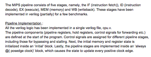
always @ (posedge clock) begin t = t + 1; if (~stall) begin // the first three pipeline stages stall if there is a load hazard //IF stage if (~takebranch) begin IFIDIR >2]; PC >2]; else if (EXMEMop == SW) DMemory[EXMEMALUOut>>2] The MIPS pipeline consists of five stages, namely, the IF (instruction fetch), ID (instruction decode), EX (execute), MEM (memory) and WB (writeback). These stages have been implemented in verilog (partially) for a few benchmarks. Pipeline Implementation All the verilog logic has been implemented in a single verilog file, cpu.v. The pipeline components (pipeline registers, hold registers, control signals for forwarding etc.) are defined at the start of the program. Control signals are assigned for different pipeline stages, including those for bypassing and stalling. Next, the initial memory and register state is initialized inside an 'initial' block. Lastly, the pipeline stages are implemented inside an 'always ( posedge clock) block, which causes the state to update every positive clock edge. The MIPS pipeline consists of five stages, namely, the IF (instruction fetch), ID (instruction decode), EX (execute), MEM (memory) and WB (writeback). These stages have been implemented in verilog (partially) for a few benchmarks. Pipeline Implementation All the verilog logic has been implemented in a single verilog file, cpu.v. The pipeline components (pipeline registers, hold registers, control signals for forwarding etc.) are defined at the start of the program. Control signals are assigned for different pipeline stages, including those for bypassing and stalling. Next, the initial memory and register state is initialized inside an 'initial' block. Lastly, the pipeline stages are implemented inside an 'always ( posedge clock) block, which causes the state to update every positive clock edge
Step by Step Solution
There are 3 Steps involved in it

Get step-by-step solutions from verified subject matter experts