

Question: Transfer the given logic gate circuit with the inputs A, B, and C and the outputs Y and Z, according to figure 3.1, to a
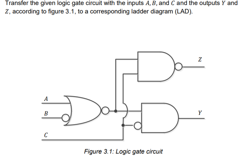
Transfer the given logic gate circuit with the inputs A, B, and C and the outputs Y and Z, according to figure 3.1, to a corresponding ladder diagram (LAD). Z B Y D C Figure 3.1: Logic gate circuit
Step by Step Solution
There are 3 Steps involved in it
1 Expert Approved Answer
Step: 1 Unlock

Question Has Been Solved by an Expert!
Get step-by-step solutions from verified subject matter experts
Step: 2 Unlock
Step: 3 Unlock