

Question: Two liquid storage systems are shown in Figure 3. Each tank is 4 feet in diameter. For System I, the valve acts as a linear
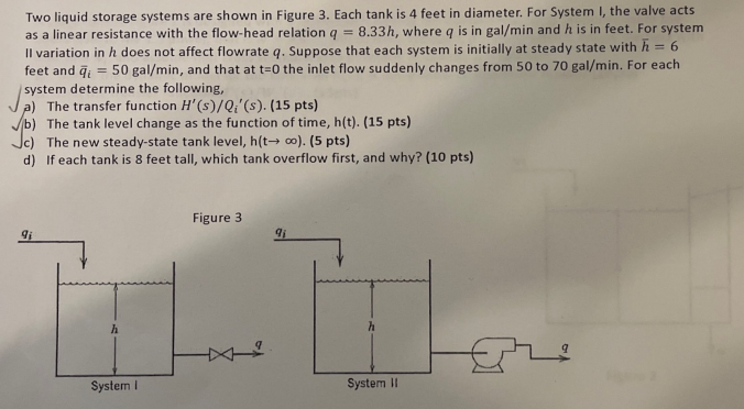
Two liquid storage systems are shown in Figure 3. Each tank is 4 feet in diameter. For System I, the valve acts as a linear resistance with the flow-head relation q = 8.33h, where q is in gal/min and his in feet. For system Il variation in h does not affect flowrate q. Suppose that each system is initially at steady state with h = 6 feet and = 50 gal/min, and that at t=0 the inlet flow suddenly changes from 50 to 70 gal/min. For each system determine the following, a) The transfer function H'(s)/Q;'(s). (15 pts) b) The tank level change as the function of time, h(t). (15 pts) Jc) The new steady-state tank level, h(t). (5 pts) d) If each tank is 8 feet tall, which tank overflow first, and why? (10 pts) Figure 3 91 91 h h L System System 11 Two liquid storage systems are shown in Figure 3. Each tank is 4 feet in diameter. For System I, the valve acts as a linear resistance with the flow-head relation q = 8.33h, where q is in gal/min and his in feet. For system Il variation in h does not affect flowrate q. Suppose that each system is initially at steady state with h = 6 feet and = 50 gal/min, and that at t=0 the inlet flow suddenly changes from 50 to 70 gal/min. For each system determine the following, a) The transfer function H'(s)/Q;'(s). (15 pts) b) The tank level change as the function of time, h(t). (15 pts) Jc) The new steady-state tank level, h(t). (5 pts) d) If each tank is 8 feet tall, which tank overflow first, and why? (10 pts) Figure 3 91 91 h h L System System 11
Step by Step Solution
There are 3 Steps involved in it

Get step-by-step solutions from verified subject matter experts