

Question: Problem 6 : Two liquid storage systems are shown in Fig. E 5 . 9 . Each tank has an area of 9 4 .
Problem :
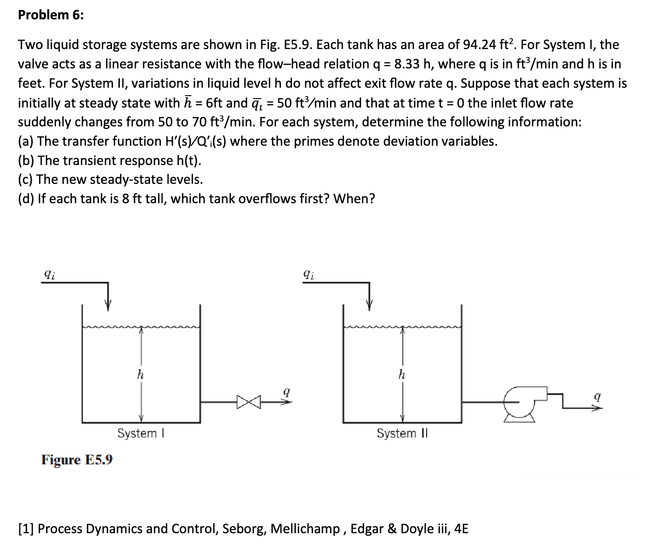
Two liquid storage systems are shown in Fig. E Each tank has an area of For System I, the
valve acts as a linear resistance with the flowhead relation where is in and is in
feet. For System II variations in liquid level do not affect exit flow rate q Suppose that each system is
initially at steady state with and and that at time the inlet flow rate
suddenly changes from to For each system, determine the following information:
a The transfer function where the primes denote deviation variables.
b The transient response
c The new steadystate levels.
d If each tank is tall, which tank overflows first? When?
r ngure evos
Process Dynamics and Control, Seborg, Mellichamp Edgar & Doyle iii, E
please tell me the step by step solution for each especially for a I dont understand how the transfer function is created, the answer has be solved before but they all have C in it which I dont understand. Can you please make it more understandable
Step by Step Solution
There are 3 Steps involved in it
1 Expert Approved Answer
Step: 1 Unlock

Question Has Been Solved by an Expert!
Get step-by-step solutions from verified subject matter experts
Step: 2 Unlock
Step: 3 Unlock