

Question: Using a table similar to that shown in Figure 3.10 of textbook, divide 55 by 12 by using the hardware described in Figure 3.8. Assume
Using a table similar to that shown in Figure 3.10 of textbook, divide 55 by 12 by using the hardware described in Figure 3.8. Assume both numbers are unsigned 6-bit integers. Draw the hardware implementation of the algorithm and show each register contents at each step.
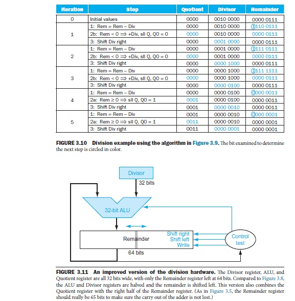
toration stop quotient Divisor Romainder o initial values 0000 0010 0000 00000111 T110 01111 1: Rem Div 0010 0000 3: Shift Div right 0001 0000 00000111 1: Rem Div 0001 0000 3: Shift Div right 0000 1000 0000 0111 1: Rem Div 0000 1000 3: Shift Div right 0000 0000 0100 0000 0111 0000 0011 1: Rem Rem Div 0000 0100 2a: Rem 20 sil Q, QO 31 3: Shift Div right 0001 0000 0010 00000011 00000001 1: Rem Div 0001 00000010 2a: Rem 20 sil Q, G20 31 3: Shift Div right 0011 0000 0001 0000 0001 FIGURE 3.10 Division example using the algorithm in Figure 3.9. The bit examined to determine the next step is circled in color. 32 bits 32-bit ALU test 64 bits FIGURE 3.11 An improved version of the division hardware. The Divisor register, ALU, and Quotient register are all 32 bits wide, with only the Remainder register left at 64 bits. Compared to Figure 3.8, the ALU and Divisor registers are halved and the remainder is shifted left. This version also combines the Quotient register with the right half of the Remainder register. (As in Figure 3.5, the Remainder register should really be 65 bits to make sure the carry out of the adder is not lost.)
Step by Step Solution
There are 3 Steps involved in it

Get step-by-step solutions from verified subject matter experts