

Question: Using modelsim Design a very simple Arithmetic and Logic Unit (ALU) that implements 8 functions as described in Table 1. Table 1 also illustrates the
Using modelsim
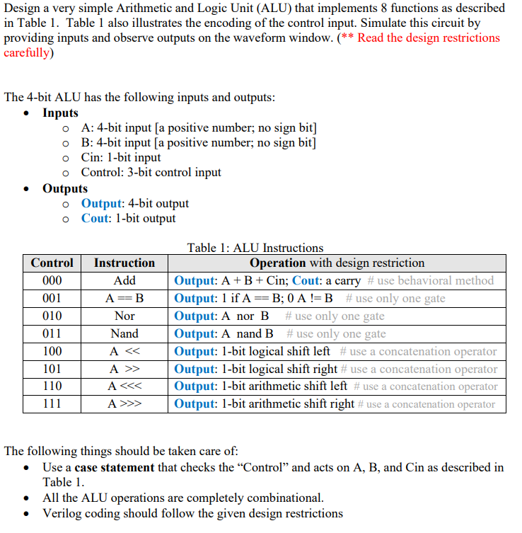
Design a very simple Arithmetic and Logic Unit (ALU) that implements 8 functions as described in Table 1. Table 1 also illustrates the encoding of the control input. Simulate this circuit by providing inputs and observe outputs on the waveform window. (** Read the design restrictions carefully) The 4-bit ALU has the following inputs and outputs: Inputs O A: 4-bit input (a positive number; no sign bit] o B: 4-bit input a positive number; no sign bit] o Cin: 1-bit input o Control: 3-bit control input Outputs o Output: 4-bit output o Cout: 1-bit output Table 1: ALU Instructions Control Instruction Operation with design restriction 000 Add Output: A+B + Cin; Cout: a carry # use behavioral method 001 A== B Output: 1 if A==B; 0 A !=B #use only one gate 010 Nor Output: A nor B # use only one gate 011 Nand Output: A nand B #use only one gate 100 A> Output: 1-bit logical shift right # use a concatenation operator 110 A>> Output: 1-bit arithmetic shift right # use a concatenation operator The following things should be taken care of: Use a case statement that checks the Control and acts on A, B, and Cin as described in Table 1. All the ALU operations are completely combinational. Verilog coding should follow the given design restrictions Design a very simple Arithmetic and Logic Unit (ALU) that implements 8 functions as described in Table 1. Table 1 also illustrates the encoding of the control input. Simulate this circuit by providing inputs and observe outputs on the waveform window. (** Read the design restrictions carefully) The 4-bit ALU has the following inputs and outputs: Inputs O A: 4-bit input (a positive number; no sign bit] o B: 4-bit input a positive number; no sign bit] o Cin: 1-bit input o Control: 3-bit control input Outputs o Output: 4-bit output o Cout: 1-bit output Table 1: ALU Instructions Control Instruction Operation with design restriction 000 Add Output: A+B + Cin; Cout: a carry # use behavioral method 001 A== B Output: 1 if A==B; 0 A !=B #use only one gate 010 Nor Output: A nor B # use only one gate 011 Nand Output: A nand B #use only one gate 100 A> Output: 1-bit logical shift right # use a concatenation operator 110 A>> Output: 1-bit arithmetic shift right # use a concatenation operator The following things should be taken care of: Use a case statement that checks the Control and acts on A, B, and Cin as described in Table 1. All the ALU operations are completely combinational. Verilog coding should follow the given design restrictions
Step by Step Solution
There are 3 Steps involved in it

Get step-by-step solutions from verified subject matter experts