

Question: Using Scheme in DrRacket please. ;Q1 ; enter your code here: ; Test cases (display AND-Gate Output ) (AND-gate 0 0) (AND-gate 0 1) (AND-gate
Using Scheme in DrRacket please.
;Q1 ; enter your code here:
; Test cases (display "AND-Gate Output ") (AND-gate 0 0) (AND-gate 0 1) (AND-gate 1 0) (AND-gate 1 1) ; Expected outputs ;0 ;0 ;0 ;1 ; Test cases (display "OR-Gate Output ") (OR-gate 0 0) (OR-gate 0 1) (OR-gate 1 0) (OR-gate 1 1) ; Expected outputs ;0 ;1 ;1 ;1 ; Test cases (display "NOT-Gate Output ") (NOT-gate 0) (NOT-gate 1) ; Expected outputs ;1 ;0
; Q1.2 ; enter your code here:
; Test cases (display "XOR-Gate Output ") (XOR-gate 0 0) (XOR-gate 0 1) (XOR-gate 1 0) (XOR-gate 1 1) ; Expected outputs ;0 ;1 ;1 ;0
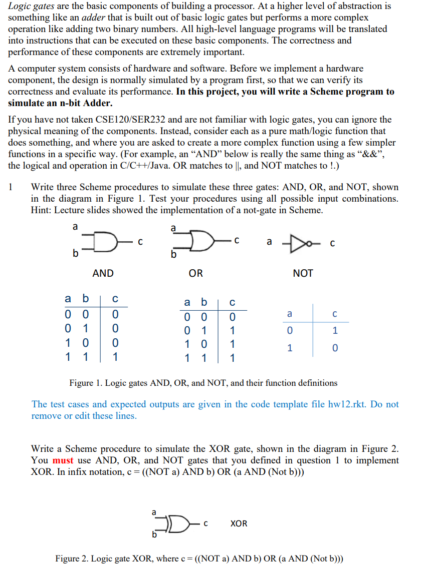
Logic gates are the basic components of building a processor. At a higher level of abstraction is something like an adder that is built out of basic logic gates but performs a more complex operation like adding two binary numbers. All high-level language programs will be translated into instructions that can be executed on these basic components. The correctness and performance of these components are extremely important. A computer system consists of hardware and software. Before we implement a hardware component, the design is normally simulated by a program first, so that we can verify its correctness and evaluate its performance. In this project, you will write a Scheme program to simulate an n-bit Adder. If you have not taken CSE120/SER232 and are not familiar with logic gates, you can ignore the physical meaning of the components. Instead, consider each as a pure math/logic function that does something, and where you are asked to create a more complex function using a few simpler functions in a specific way. (For example, an "AND" below is really the same thing as "\&\&", the logical and operation in C/C++/Java. OR matches to , and NOT matches to !.) 1 Write three Scheme procedures to simulate these three gates: AND, OR, and NOT, shown in the diagram in Figure 1. Test your procedures using all possible input combinations. Hint: Lecture slides showed the implementation of a not-gate in Scheme. Figure 1. Logic gates AND, OR, and NOT, and their function definitions The test cases and expected outputs are given in the code template file hw12.rkt. Do not remove or edit these lines. Write a Scheme procedure to simulate the XOR gate, shown in the diagram in Figure 2. You must use AND, OR, and NOT gates that you defined in question 1 to implement XOR. In infix notation, c=(( NOT a ) AND b) OR ( a AND ( Not b ))) Figure 2. Logic gate XOR, where c=(( NOT a) AND b ) OR (a AND ( Not b )))
Step by Step Solution
There are 3 Steps involved in it

Get step-by-step solutions from verified subject matter experts