

Question: Using this transition table ( in image ) : Draw a schematic that implements the state machine in digital logic. Use two flip - flops
Using this transition table in image: Draw a schematic that implements the state machine in digital logic. Use two flipflops to hold
the state, and basic gates AND OR NOT, NAND, NOR for the nextstate logic and output logic.
You likely first need to derive expressions for these pieces of logic, which you can do in any way
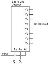
you want. Then using the graphic with the decoder, Fill in the middle of this schematic with gates needed to implement your state machines
behavior.
Step by Step Solution
There are 3 Steps involved in it
1 Expert Approved Answer
Step: 1 Unlock

Question Has Been Solved by an Expert!
Get step-by-step solutions from verified subject matter experts
Step: 2 Unlock
Step: 3 Unlock