

Question: using Verilog create code these of test benches thank you The second type of testbench has to be of type 3 with test vectors. Enter
using Verilog create code these of test benches thank you
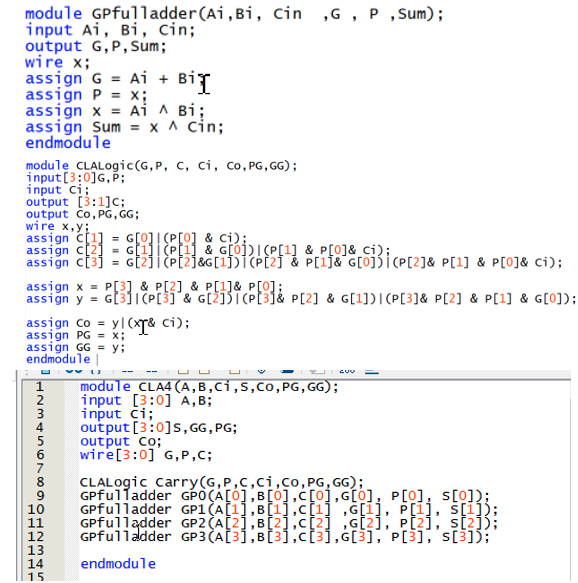
The second type of testbench has to be of type 3 with test vectors. Enter your possible inputs and expected outputs as binary entries in a separate file called test_vector.tv, and follow the steps to generate the test bench. Use the test_vector_tb as a starting point for your testbench Verilog code. Remember that the testbench code is not sythesizable. module GPfulladder(Ai,Bi, cin ,G, P , Sum); input Ai, Bi, cin; output G, P, Sum; wire x; assign G = Ai + Bil assign P = x; assign X = Ai i Bi; assign Sum = x 1 cin; endmodule module Chalogic(G, P, C, ci, Co, PG, GG); input[3:0]G,P; input ci; output [3:1]c; output Co, PG, GG; wire x,y; assign (11) = G[O] (P[O] & ci); assign C:21 = Gaji (Pi) & GLD) IP[1] & P[0]& ci); assign ct3j = G2iPE2&[1])i (P2j & P[i]& G[oji (P[2]& P[1] & P[0]& ci); assign x = P[3] & P[2] & P[1]& P[0]; assign = GE311 CP[3] & [ji (Plje P[2] & [1]) (P[3]& P[2] & P[1] & G[0]); assign co = y (T& c); assign PG = x; assign GG = y; endmodule module CLA4 (A,B,Ci,s,Co, PG, GG); 2 input [3:0] A,B; 3 input ci; output[3:0]s, GG,PG; output co; 6 wire [3:0] G,P,C; 7 CLALogic Carry(G,P,C,CI,CO,PG, GG); 9 GPfulladder GPO (A[O],[0].C[0],[0], P[0], s[0]); 10 GPfulladder GP1 A[1],[1],c[1] ,G[i], P[i], s[i]); 11 GPfulladder GP2A(2),B12),C[2] ;G[2], p[2] s[2]); 12 GPfulladder GP3 (A31,B[31,c[3],[3], P[3], [3]); 13 endmodule 15 SUU 1 The second type of testbench has to be of type 3 with test vectors. Enter your possible inputs and expected outputs as binary entries in a separate file called test_vector.tv, and follow the steps to generate the test bench. Use the test_vector_tb as a starting point for your testbench Verilog code. Remember that the testbench code is not sythesizable. module GPfulladder(Ai,Bi, cin ,G, P , Sum); input Ai, Bi, cin; output G, P, Sum; wire x; assign G = Ai + Bil assign P = x; assign X = Ai i Bi; assign Sum = x 1 cin; endmodule module Chalogic(G, P, C, ci, Co, PG, GG); input[3:0]G,P; input ci; output [3:1]c; output Co, PG, GG; wire x,y; assign (11) = G[O] (P[O] & ci); assign C:21 = Gaji (Pi) & GLD) IP[1] & P[0]& ci); assign ct3j = G2iPE2&[1])i (P2j & P[i]& G[oji (P[2]& P[1] & P[0]& ci); assign x = P[3] & P[2] & P[1]& P[0]; assign = GE311 CP[3] & [ji (Plje P[2] & [1]) (P[3]& P[2] & P[1] & G[0]); assign co = y (T& c); assign PG = x; assign GG = y; endmodule module CLA4 (A,B,Ci,s,Co, PG, GG); 2 input [3:0] A,B; 3 input ci; output[3:0]s, GG,PG; output co; 6 wire [3:0] G,P,C; 7 CLALogic Carry(G,P,C,CI,CO,PG, GG); 9 GPfulladder GPO (A[O],[0].C[0],[0], P[0], s[0]); 10 GPfulladder GP1 A[1],[1],c[1] ,G[i], P[i], s[i]); 11 GPfulladder GP2A(2),B12),C[2] ;G[2], p[2] s[2]); 12 GPfulladder GP3 (A31,B[31,c[3],[3], P[3], [3]); 13 endmodule 15 SUU 1
Step by Step Solution
There are 3 Steps involved in it

Get step-by-step solutions from verified subject matter experts