

Question: V. Coflow microfluidic viscometer. The figure below shows two Newtonian fluid streams coflowing next to each other, where one of the fluids is dyed. The
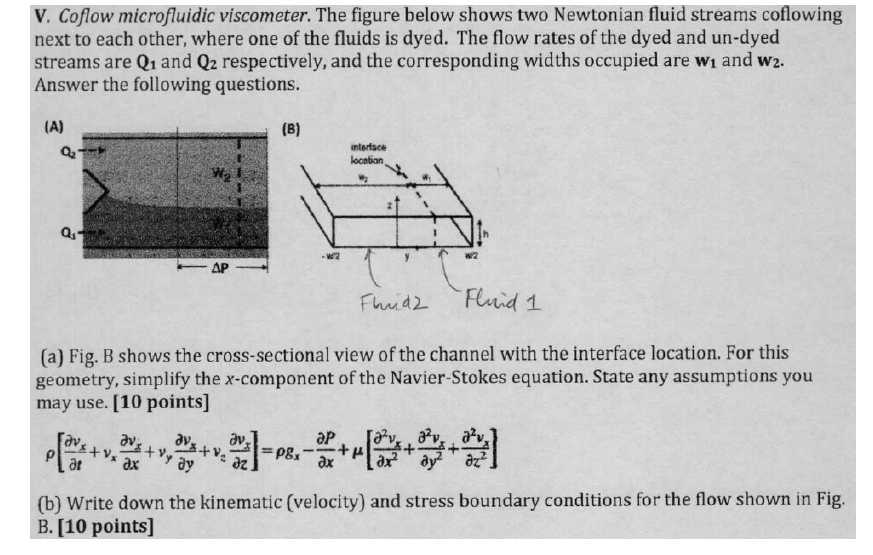
V. Coflow microfluidic viscometer. The figure below shows two Newtonian fluid streams coflowing next to each other, where one of the fluids is dyed. The flow rates of the dyed and un-dyed streams are Q1 and Q2 respectively, and the corresponding widths occupied are w1 and W2. Answer the following questions. (a) Fig. B shows the cross-sectional view of the channel with the interface location. For this geometry, simplify the x-component of the Navier-Stokes equation. State any assumptions you may use. [10 points ] [tvx+vxxvx+vyyvx+vzzvx]=gxxP+[x22vx+y22vx+z22vx] (b) Write down the kinematic (velocity) and stress boundary conditions for the flow shown in Fig. B. [10 points]
Step by Step Solution
There are 3 Steps involved in it

Get step-by-step solutions from verified subject matter experts