

Question: Verilog with testbench please Design: The schematic given in figure 2 explains only the carry logic in a 4-bit look ahead adder. You will need
Verilog with testbench please 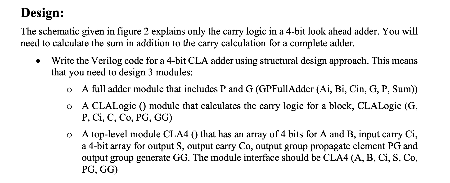
Design: The schematic given in figure 2 explains only the carry logic in a 4-bit look ahead adder. You will need to calculate the sum in addition to the carry calculation for a complete adder. Write the Verilog code for a 4-bit CLA adder using structural design approach. This means that you need to design 3 modules: A full adder module that includes P and G (GPFullAdder (Ai, Bi, Cin, G, P, Sum)) O A CLALogic () module that calculates the carry logic for a block, CLALogic (G, P, Ci, C, Co, PG, GG) A top-level module CLA4 () that has an array of 4 bits for A and B, input carry Ci, a 4-bit array for output S, output carry Co, output group propagate element PG and output group generate GG. The module interface should be CLA4 (A, B, Ci, S, Co, PG, GG) O Design: The schematic given in figure 2 explains only the carry logic in a 4-bit look ahead adder. You will need to calculate the sum in addition to the carry calculation for a complete adder. Write the Verilog code for a 4-bit CLA adder using structural design approach. This means that you need to design 3 modules: A full adder module that includes P and G (GPFullAdder (Ai, Bi, Cin, G, P, Sum)) O A CLALogic () module that calculates the carry logic for a block, CLALogic (G, P, Ci, C, Co, PG, GG) A top-level module CLA4 () that has an array of 4 bits for A and B, input carry Ci, a 4-bit array for output S, output carry Co, output group propagate element PG and output group generate GG. The module interface should be CLA4 (A, B, Ci, S, Co, PG, GG) O
Step by Step Solution
There are 3 Steps involved in it

Get step-by-step solutions from verified subject matter experts