

Question: We need to design and implement the circuit with the ASM chart below SO Count n; Key + 0; cText = 0 reset 0
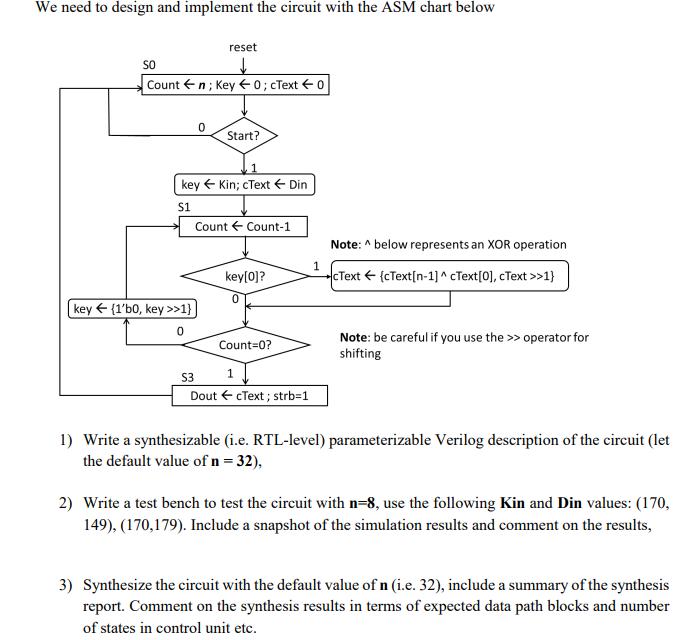
We need to design and implement the circuit with the ASM chart below SO Count n; Key + 0; cText = 0 reset 0 key {1'b0, key >>1} 0 Start? key Kin; cText Din S1 Count Count-1 key[0]? 0 Count=0? 1 $3 Dout cText; strb=1 1 Note: ^ below represents an XOR operation cText {cText[n-1]^cText[0], cText >>1} Note: be careful if you use the >> operator for shifting 1) Write a synthesizable (i.e. RTL-level) parameterizable Verilog description of the circuit (let the default value of n = 32), 2) Write a test bench to test the circuit with n=8, use the following Kin and Din values: (170, 149), (170,179). Include a snapshot of the simulation results and comment on the results, 3) Synthesize the circuit with the default value of n (i.e. 32), include a summary of the synthesis report. Comment on the synthesis results in terms of expected data path blocks and number of states in control unit etc.
Step by Step Solution
There are 3 Steps involved in it
1 Synthesizable Verilog Description The following is the synthesizable Veril... View full answer

Get step-by-step solutions from verified subject matter experts