

Question: We studied Event Driven Timing Simulation (EDTS) in class. Refer to page 12.1 to 12.2 of the annotated class notes on Verilog. In this question,
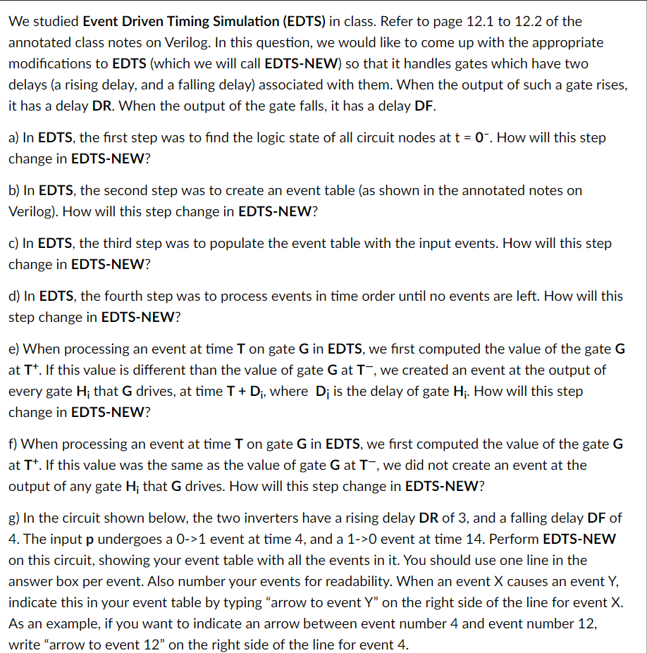
We studied Event Driven Timing Simulation (EDTS) in class. Refer to page 12.1 to 12.2 of the annotated class notes on Verilog. In this question, we would like to come up with the appropriate modifications to EDTS (which we will call EDTS-NEW) so that it handles gates which have two delays (a rising delay, and a falling delay) associated with them. When the output of such a gate rises, it has a delay DR. When the output of the gate falls, it has a delay DF. a) In EDTS, the first step was to find the logic state of all circuit nodes at t = 0". How will this step change in EDTS-NEW? b) In EDTS, the second step was to create an event table (as shown in the annotated notes on Verilog). How will this step change in EDTS-NEW? c) In EDTS, the third step was to populate the event table with the input events. How will this step change in EDTS-NEW? d) In EDTS, the fourth step was to process events in time order until no events are left. How will this step change in EDTS-NEW? e) When processing an event at time T on gate G in EDTS, we first computed the value of the gate G at Tt. If this value is different than the value of gate G at T , we created an event at the output of every gate H; that G drives, at time T +D;, where Di is the delay of gate Hj. How will this step change in EDTS-NEW? f) When processing an event at time T on gate G in EDTS, we first computed the value of the gate G at Tt. If this value was the same as the value of gate G at T , we did not create an event at the output of any gate H; that G drives. How will this step change in EDTS-NEW? g) In the circuit shown below, the two inverters have a rising delay DR of 3, and a falling delay DF of 4. The input p undergoes a 0->1 event at time 4, and a 1->0 event at time 14. Perform EDTS-NEW on this circuit, showing your event table with all the events in it. You should use one line in the answer box per event. Also number your events for readability. When an event X causes an event Y, indicate this in your event table by typing "arrow to event Y on the right side of the line for event X. As an example, if you want to indicate an arrow between event number 4 and event number 12, write "arrow to event 12" on the right side of the line for event 4. We studied Event Driven Timing Simulation (EDTS) in class. Refer to page 12.1 to 12.2 of the annotated class notes on Verilog. In this question, we would like to come up with the appropriate modifications to EDTS (which we will call EDTS-NEW) so that it handles gates which have two delays (a rising delay, and a falling delay) associated with them. When the output of such a gate rises, it has a delay DR. When the output of the gate falls, it has a delay DF. a) In EDTS, the first step was to find the logic state of all circuit nodes at t = 0". How will this step change in EDTS-NEW? b) In EDTS, the second step was to create an event table (as shown in the annotated notes on Verilog). How will this step change in EDTS-NEW? c) In EDTS, the third step was to populate the event table with the input events. How will this step change in EDTS-NEW? d) In EDTS, the fourth step was to process events in time order until no events are left. How will this step change in EDTS-NEW? e) When processing an event at time T on gate G in EDTS, we first computed the value of the gate G at Tt. If this value is different than the value of gate G at T , we created an event at the output of every gate H; that G drives, at time T +D;, where Di is the delay of gate Hj. How will this step change in EDTS-NEW? f) When processing an event at time T on gate G in EDTS, we first computed the value of the gate G at Tt. If this value was the same as the value of gate G at T , we did not create an event at the output of any gate H; that G drives. How will this step change in EDTS-NEW? g) In the circuit shown below, the two inverters have a rising delay DR of 3, and a falling delay DF of 4. The input p undergoes a 0->1 event at time 4, and a 1->0 event at time 14. Perform EDTS-NEW on this circuit, showing your event table with all the events in it. You should use one line in the answer box per event. Also number your events for readability. When an event X causes an event Y, indicate this in your event table by typing "arrow to event Y on the right side of the line for event X. As an example, if you want to indicate an arrow between event number 4 and event number 12, write "arrow to event 12" on the right side of the line for event 4
Step by Step Solution
There are 3 Steps involved in it

Get step-by-step solutions from verified subject matter experts