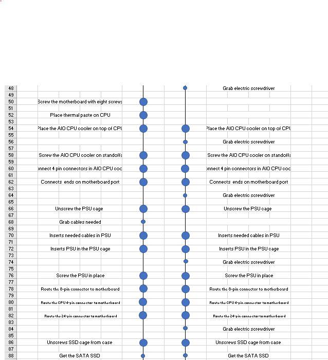
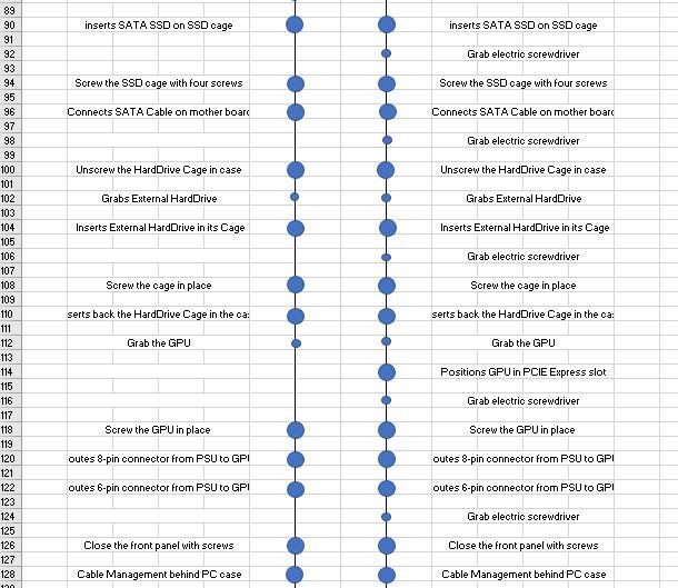
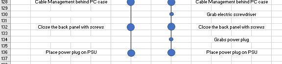
Question: Work study. Please make an alternative method using this current chart (Operation chart) A B C E F J K L M N G H

Work study. Please make an alternative method using this current chart (Operation chart) Work study. Please make an alternative methodWork study. Please make an alternative methodWork study. Please make an alternative methodWork study. Please make an alternative method

A B C E F J K L M N G H CURRENT METHOD 6 7 8 9 LEFT HAND RIGHT HAND Position motherboard on the workplace Position motherboard on the workplace Opens CPU socket cover Open the CPU socket cover Grabs the CPU Grabs the CPU 10 11 12 13 14 15 16 17 18 19 20 21 Attach the CPU on the socket Closes CPU socket Closes CPU socket Peel the plastic from the motherboard Grab the electric screwdriver Unscrew two screws on SSD slot Unscrew two screws on SSD slot Insert NVMe SSD into NVMe SSD slot Screw the SSD in place Peel the thermal pad on SSD slot cover Cover the SSD slot Cover the SSD slot Grab four RAM stioks Grab four RAM sticks 23 24 25 26 27 28 29 30 31 32 33 34 35 36 37 38 39 40 41 42 43 44 45 46 47 Insert the RAM sticks into their slots Insert the RAM sticks into their slots Insert standoff screws for CPU cooler Positions PC oase on the workplace Positions PC oase on the workplace Grab the IO shied Grab the lo shied Positions 10 shield in PC Case Positions I shield in PC Case Positions motherboard on the PC case Positions motherboard on the PC case Grab electric screwdriver Bcrew the motherboard with eight screws Place thermal paste on CPU Place the AIO CPU cooler on top of CPI Place the AIO CPU cooler on top of CPL Grab electric screwdriver Screw the AIO CPU cooler on standoffs Screw the AIO CPU cooler on standoffs Onnect 4 pin connectors in AIO CPU cod onnect 4 pin connectors in AID CPU COC Connects ends on motherboard port Connects ends on motherboard port Grab electric screwdriver Unscrew the PSUC cage Unscrew the PSU cage 48 49 50 51 52 53 54 55 56 57 58 59 60 61 62 63 64 65 66 67 68 69 70 71 72 73 74 75 76 77 78 79 80 81 82 83 84 85 86 87 88 Grab cables needed Inserts needed cables in PSU Inserts needed cables in PSU Inserts PSU in the PSU cage Inserts PSU in the PSU cage Grab electric screwdriver Screw the PSU in place Screw the PSU in place Route the 8-pin connector to motherboard Route the 8-pin connector to motherboard Route the CPU 4-pin connector to motherboard Routo the CPU 4-pin connector to motherboard Rauto the 24-pin connector to motherboard Route the 24-pin connector to motherboard Grab electric screwdriver Unscrews SSD cage from case Unscrews SSD oage from case Get the SATA SSD Get the SATA SSD inserts SATA SSD on SSD cage inserts SATA SSD on SSD cage Grab electric screwdriver Screw the SSD cage with four screws Screw the SSD cage with four screws Connects SATA Cable on motherboard Connects SATA Cable on motherboard Grab electric screwdriver Unscrew the Hard Drive Cage in case Unscrew the Hard Drive Cage in oase Grabs External Hard Drive Grabs External Hard Drive Inserts External Hard Drive in its Cage Inserts External Hard Drive in its Cage Grab electric screwdriver Screw the cage in place Screw the cage in place 89 90 91 92 93 94 95 96 97 98 99 100 101 102 103 104 105 106 107 108 109 110 111 112 113 114 115 116 117 118 119 120 121 122 123 124 125 126 127 128 120 . serts back the HardDrive Cage in the ca: serts back the Hard Drive Cage in the ca: Grab the GPU Grab the GPU Positions GPU in PCIE Express slot Grab electric screwdriver Screw the GPU in place Screw the GPU in place outes 8-pin connector from PSU to GPI outes 8-pin connector from PSU to GPI outes 6-pin connector from PSU to GPI outes 6-pin connector from PSU to GPI Grab electric screwdriver Close the front panel with screws Close the front panel with screws Cable Management behind PC case Cable Management behind PC case Cable Management behind PC case Cable Management behind PC case Grab electric screwdriver Close the back panel with screws Close the back panel with screws 128 129 130 131 132 133 134 135 136 137 Grabs power plug Place power plug on PSU Place power plug on PSU A B C E F J K L M N G H CURRENT METHOD 6 7 8 9 LEFT HAND RIGHT HAND Position motherboard on the workplace Position motherboard on the workplace Opens CPU socket cover Open the CPU socket cover Grabs the CPU Grabs the CPU 10 11 12 13 14 15 16 17 18 19 20 21 Attach the CPU on the socket Closes CPU socket Closes CPU socket Peel the plastic from the motherboard Grab the electric screwdriver Unscrew two screws on SSD slot Unscrew two screws on SSD slot Insert NVMe SSD into NVMe SSD slot Screw the SSD in place Peel the thermal pad on SSD slot cover Cover the SSD slot Cover the SSD slot Grab four RAM stioks Grab four RAM sticks 23 24 25 26 27 28 29 30 31 32 33 34 35 36 37 38 39 40 41 42 43 44 45 46 47 Insert the RAM sticks into their slots Insert the RAM sticks into their slots Insert standoff screws for CPU cooler Positions PC oase on the workplace Positions PC oase on the workplace Grab the IO shied Grab the lo shied Positions 10 shield in PC Case Positions I shield in PC Case Positions motherboard on the PC case Positions motherboard on the PC case Grab electric screwdriver Bcrew the motherboard with eight screws Place thermal paste on CPU Place the AIO CPU cooler on top of CPI Place the AIO CPU cooler on top of CPL Grab electric screwdriver Screw the AIO CPU cooler on standoffs Screw the AIO CPU cooler on standoffs Onnect 4 pin connectors in AIO CPU cod onnect 4 pin connectors in AID CPU COC Connects ends on motherboard port Connects ends on motherboard port Grab electric screwdriver Unscrew the PSUC cage Unscrew the PSU cage 48 49 50 51 52 53 54 55 56 57 58 59 60 61 62 63 64 65 66 67 68 69 70 71 72 73 74 75 76 77 78 79 80 81 82 83 84 85 86 87 88 Grab cables needed Inserts needed cables in PSU Inserts needed cables in PSU Inserts PSU in the PSU cage Inserts PSU in the PSU cage Grab electric screwdriver Screw the PSU in place Screw the PSU in place Route the 8-pin connector to motherboard Route the 8-pin connector to motherboard Route the CPU 4-pin connector to motherboard Routo the CPU 4-pin connector to motherboard Rauto the 24-pin connector to motherboard Route the 24-pin connector to motherboard Grab electric screwdriver Unscrews SSD cage from case Unscrews SSD oage from case Get the SATA SSD Get the SATA SSD inserts SATA SSD on SSD cage inserts SATA SSD on SSD cage Grab electric screwdriver Screw the SSD cage with four screws Screw the SSD cage with four screws Connects SATA Cable on motherboard Connects SATA Cable on motherboard Grab electric screwdriver Unscrew the Hard Drive Cage in case Unscrew the Hard Drive Cage in oase Grabs External Hard Drive Grabs External Hard Drive Inserts External Hard Drive in its Cage Inserts External Hard Drive in its Cage Grab electric screwdriver Screw the cage in place Screw the cage in place 89 90 91 92 93 94 95 96 97 98 99 100 101 102 103 104 105 106 107 108 109 110 111 112 113 114 115 116 117 118 119 120 121 122 123 124 125 126 127 128 120 . serts back the HardDrive Cage in the ca: serts back the Hard Drive Cage in the ca: Grab the GPU Grab the GPU Positions GPU in PCIE Express slot Grab electric screwdriver Screw the GPU in place Screw the GPU in place outes 8-pin connector from PSU to GPI outes 8-pin connector from PSU to GPI outes 6-pin connector from PSU to GPI outes 6-pin connector from PSU to GPI Grab electric screwdriver Close the front panel with screws Close the front panel with screws Cable Management behind PC case Cable Management behind PC case Cable Management behind PC case Cable Management behind PC case Grab electric screwdriver Close the back panel with screws Close the back panel with screws 128 129 130 131 132 133 134 135 136 137 Grabs power plug Place power plug on PSU Place power plug on PSU

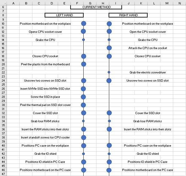
Step by Step Solution

There are 3 Steps involved in it

1 Expert Approved Answer
Step: 1 Unlock blur-text-image
Question Has Been Solved by an Expert!

Get step-by-step solutions from verified subject matter experts

Step: 2 Unlock
Step: 3 Unlock

Students Have Also Explored These Related General Management Questions!