

Question: Working in a stable state at the beginning and inside V=2 m3 solution-containing heated-stirred tank Fi=0.1 (m3 The solution is fed at a temperature of
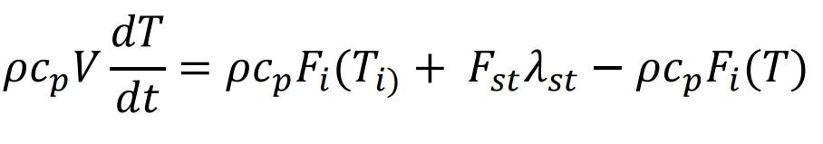
Working in a stable state at the beginning and inside V=2 m3 solution-containing heated-stirred tank Fi=0.1 (m3 The solution is fed at a temperature of Ti = 30 C with a flow rate of /min) and saturated steam at a flow rate of Fst=4 kg/min. is heated using Saturated steam enters the system at Tst=110 C and leaves the system at the same temperature. It comes out as a saturated liquid. The latent heat of condensation (st) of steam at the specified temperature is 2256 kJ/kg. An effective mixing is done in the boiler and due to the insulation There is no heat loss to the environment. Specific heat of solution cp=3.85 kJ/kg K and its density =1035 kg/m3 it is. with process time The dynamic model describing the temperature change is given below. a) Transfer function of the process and process block diagram create it. (10p) b) If the temperature of the feed solution rises to Ti=40 C (10 unit step increase) of the outlet temperature (T) at the new steady state find its value. (15p) Dynamic model of the process: Energy Accumulated in the System = Energy Entered into the System-Energy Out of the System
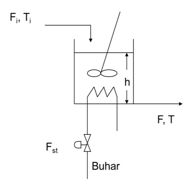
In the heating process defined in Question 1, the temperature of the solution is controlled by adjusting the steam flow. is desired. For this purpose, a Feedback Control system will be designed and a temperature sensor (thermal couple) and a control valve will be placed in the steam line. Process and control The transfer functions describing the behavior of the system elements are given below.
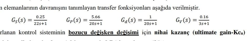
a) Ultimate gain (Kcu) for the disturbance variable change of the designed control system Calculate its value and final period (ultimate period-Pu).(25p) NOTE: It can be used as () = at this stage. b) Calculate the PID parameters with the Ziegler-Nichols closed-loop tuning method and Obtain the characteristic equation by constructing the general (bulk) transfer function of the PID control system. Please pay. (30p) c) By reducing the block diagram of the feedback PID control system, the batch transfer function The behavior of the system as a result of a 10 C step increase in the temperature of the input stream (Ti) drawing the graph (500 sec) that defines it, finds the roots of the characteristic equation and finds its geometric location. Write the MATLAB codes that draw the diagram that defines (Root Locus). (25p)
dT - pcp pcpFi(Ti) + Fstast pcpFi(T) dt FT a h F, T Fst Buhar n elemanlarnn davrann tanmlayan transfer fonksiyonlar aada verilmitir. 0.25 5.66 1 0.16 Gs(s) = Gp(s) = Ga(s) = Gy(s) ) = 22s+1 205+1 205+1 35+1 rlanan kontrol sisteminin bozucu deiken deiimi iin nihai kazan (ultimate gain-Kcu) =
Step by Step Solution
There are 3 Steps involved in it

Get step-by-step solutions from verified subject matter experts