

Question: Write a Verilog module for the logic circuit shown below. Let us refer to this module by the name MOD1. Use gate netlist (structural modeling)
- Write a Verilog module for the logic circuit shown below. Let us refer to this module by the name MOD1. Use gate netlist (structural modeling) in your module definition of MOD1.
- Write another Verilog module the other logic circuit shown below. Let us refer to this module by the name MOD2. Use continuous assignment statement in your module definition of MOD2.
- Write a Verilog module (name it EqualityChecker) that instantiates MOD1 and MOD2. The ports definition of EqualityChecker module consists of two inputs, A and B, and one output, F. Pots of EqualityChecker are connected as follows. Port A is connected to Inputs A of MOD1 and MOD2 instances. Port B is connected to Input B of MOD1 and MOD2 instances. Port F1 (the outputs of MOD1 instance) and Port F2 (the output of MOD2 instance) feed a logic gate that outputs 1 when the value of F1 for the given A and B equals the value of F2. What do you think the gate should be? The following diagram illustrates the structure of the EqualityChecker module:Please note that you have to figure out what gate to use to detect equality of F1 and F2.
- Write a testbench module and apply all the possible 4 patterns of A and B. Show your simulation waveform and tell us whether the two instances of MOD1 and MOD2 are equivalent (equal) or not.
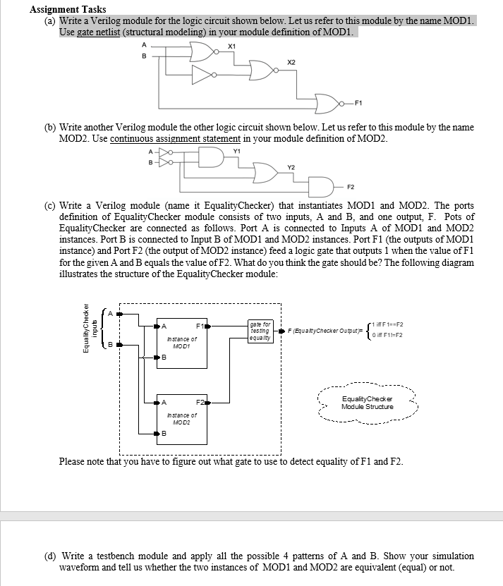
Assignment Tasks @) Write a Verilog module for the logic circuit shown below. Let us refer to this module by the name MOD1. Use gate netlist (structural modeling) in your module definition of MOD1. X1 (6) Write another Verilog module the other logic circuit shown below. Let us refer to this module by the name MOD2. Use continuous assignment statement in your module definition of MOD2. Diby F2 (C) Write a Verilog module (name it EqualityChecker) that instantiates MOD1 and MOD2. The ports definition of Equality Checker module consists of two inputs, A and B, and one output, F. Pots of EqualityChecker are connected as follows. Port A is connected to Inputs A of MODI and MOD2 instances. Port B is connected to Input B of MOD1 and MOD2 instances. Port F1 (the outputs of MOD1 instance) and Port F2 (the output of MOD2 instance) feed a logic gate that outputs 1 when the value of F1 for the given A and B equals the value of F2. What do you think the gate should be? The following diagram illustrates the structure of the Equality Checker module: Equality Checker inputs A F1) gate for testing equally F (Equality Checker Output i F1==F2 O F1-F2 Instance of MOD1 F2 EqualityChecker Module Structure Instance of MOD2 B Please note that you have to figure out what gate to use to detect equality of F1 and F2. (d) Write a testbench module and apply all the possible 4 patterns of A and B. Show your simulation waveform and tell us whether the two instances of MOD1 and MOD2 are equivalent (equal) or not
Step by Step Solution
There are 3 Steps involved in it

Get step-by-step solutions from verified subject matter experts