

Question: You are required to design a sequential circuit that controls the traffic lights at an intersection. The traffic light controller is for an intersection between
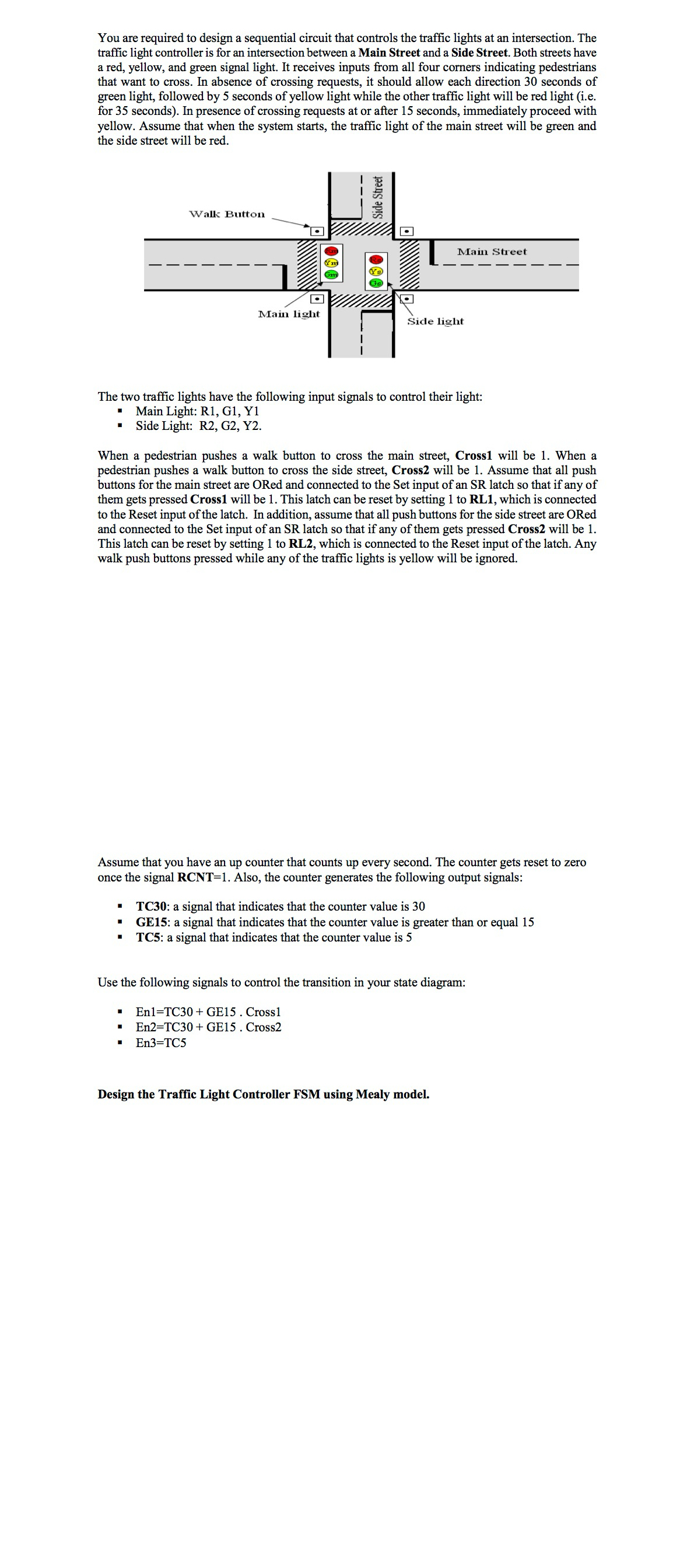
You are required to design a sequential circuit that controls the traffic lights at an intersection. The traffic light controller is for an intersection between a Main Street and a Side Street. Both streets have a red, yellow, and green signal light. It receives inputs from all four corners indicating pedestrians that want to cross. In absence of crossing requests, it should allow each direction seconds of green light, followed by seconds of yellow light while the other traffic light will be red light ie for seconds In presence of crossing requests at or after seconds, immediately proceed with yellow. Assume that when the system starts, the traffic light of the main street will be green and the side street will be red.
The two traffic lights have the following input signals to control their light:
Main Light: R G Y
Side Light: R G Y
When a pedestrian pushes a walk button to cross the main street, Cross will be When a pedestrian pushes a walk button to cross the side street, Cross will be Assume that all push buttons for the main street are ORed and connected to the Set input of an SR latch so that if any of them gets pressed Cross will be This latch can be reset by setting to RL which is connected to the Reset input of the latch. In addition, assume that all push buttons for the side street are ORed and connected to the Set input of an SR latch so that if any of them gets pressed Cross will be This latch can be reset by setting to RL which is connected to the Reset input of the latch. Any walk push buttons pressed while any of the traffic lights is yellow will be ignored.
Assume that you have an up counter that counts up every second. The counter gets reset to zero once the signal RCNT Also, the counter generates the following output signals:
TC: a signal that indicates that the counter value is
GE: a signal that indicates that the counter value is greater than or equal
TC: a signal that indicates that the counter value is
Use the following signals to control the transition in your state diagram:
EnTC GE Cross
EnTC GE Cross
EnTC
Design the Traffic Light Controller FSM using Mealy model.Draw the state digram
Step by Step Solution
There are 3 Steps involved in it
1 Expert Approved Answer
Step: 1 Unlock

Question Has Been Solved by an Expert!
Get step-by-step solutions from verified subject matter experts
Step: 2 Unlock
Step: 3 Unlock