

Question: You may assume the counter ( CNT3 ) is initially at 0, but you must return it to 0 when the you are done since
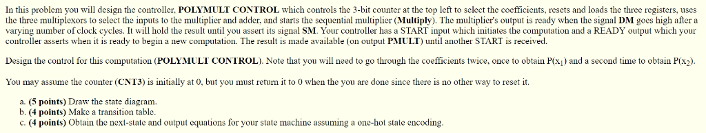
You may assume the counter (CNT3) is initially at 0, but you must return it to 0 when the you are done since there is no other way to reset it.
- (5 points) Draw the state diagram.
- (4 points) Make a transition table.
- (4 points) Obtain the next-state and output equations for your state machine assuming a one-hot state encoding.
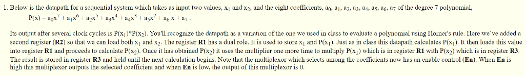
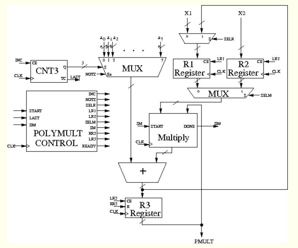
1. Below is the datapath for a sequential system which takes as input two values, x and x2, and the eight coefficients, ao. a, a2. a3. a4, a5. ag. aj of the degree 7 polynomial, Its output after several clock cycles is P(xi)*P(x2). You'll recognize the datapath as a variation of the one we used in class to evaluate a polynomial using Horner's rule. Here we've added a second register (R2) so that we can load bothxi andx2. The register R1 has a dual role. It is used to store x and P(xi). Just as in class this datapath calculates P(x. It then loads this value into register RI and proceeds to calculate P(x ). Once t has obtained P ) l uses the multiplier one more time to multiply P(xi) which is in register R1 with P(x ) which s in register R3 The result is stored in register R3 and held until the next calculation begins. Note that the multiplexor which selects among the coefficients now has an enable control (En). When En is high this multiplexor outputs the selected coefficient and when En is low, the output of this multiplexor is 0. X1 X2 ao a1a2 SELR INC 0 1 2 Ri c R2 cE CE CNT30 MUX CLK CLK NOTZ TC INC SELN START LR2 SN DN START SN POLYMULT 3 CONTROL zFD Multiply LR3 READY Register PMULT In this problem you will design the controller, POLYMULT CONTROL which controls the 3-bit counter at the top left to select the coefficients, resets and loads the three registers, uses the three multiplexors to select the inputs to the multiplier and adder, and starts the sequential multiplier (Multiply). The multiplier's output is ready when the signal DM goes high after a varying number of clock cycles. It will hold the result until you assert its signal SM. Your controller has a START input which initiates the computation and a READY output which your controller asserts when it is ready to begin a new computation. The result is made available (on output PMULT) until another START is received. Design the control or this computation (POLI IL LI CON ROL Note that you i need to g uro g the e cents twice. once i o tun o and a secon une b in s 2. You may assume the counter (CNT3) is initially at 0, but you must return it to 0 when the you are done since there is no other way to resetit a. (5 points) Draw the state diagram. b. (4 points) Make a transition table c (4 points) Obtain the next state and output equations or your state machine assumin one-hot state encoding 1. Below is the datapath for a sequential system which takes as input two values, x and x2, and the eight coefficients, ao. a, a2. a3. a4, a5. ag. aj of the degree 7 polynomial, Its output after several clock cycles is P(xi)*P(x2). You'll recognize the datapath as a variation of the one we used in class to evaluate a polynomial using Horner's rule. Here we've added a second register (R2) so that we can load bothxi andx2. The register R1 has a dual role. It is used to store x and P(xi). Just as in class this datapath calculates P(x. It then loads this value into register RI and proceeds to calculate P(x ). Once t has obtained P ) l uses the multiplier one more time to multiply P(xi) which is in register R1 with P(x ) which s in register R3 The result is stored in register R3 and held until the next calculation begins. Note that the multiplexor which selects among the coefficients now has an enable control (En). When En is high this multiplexor outputs the selected coefficient and when En is low, the output of this multiplexor is 0. X1 X2 ao a1a2 SELR INC 0 1 2 Ri c R2 cE CE CNT30 MUX CLK CLK NOTZ TC INC SELN START LR2 SN DN START SN POLYMULT 3 CONTROL zFD Multiply LR3 READY Register PMULT In this problem you will design the controller, POLYMULT CONTROL which controls the 3-bit counter at the top left to select the coefficients, resets and loads the three registers, uses the three multiplexors to select the inputs to the multiplier and adder, and starts the sequential multiplier (Multiply). The multiplier's output is ready when the signal DM goes high after a varying number of clock cycles. It will hold the result until you assert its signal SM. Your controller has a START input which initiates the computation and a READY output which your controller asserts when it is ready to begin a new computation. The result is made available (on output PMULT) until another START is received. Design the control or this computation (POLI IL LI CON ROL Note that you i need to g uro g the e cents twice. once i o tun o and a secon une b in s 2. You may assume the counter (CNT3) is initially at 0, but you must return it to 0 when the you are done since there is no other way to resetit a. (5 points) Draw the state diagram. b. (4 points) Make a transition table c (4 points) Obtain the next state and output equations or your state machine assumin one-hot state encoding
Step by Step Solution
There are 3 Steps involved in it

Get step-by-step solutions from verified subject matter experts