

Question: You will design two embedded systems with multiple inputs on one microcontroller and output via a single controller. That employs 12C communication, timer interrupts
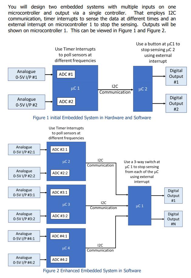
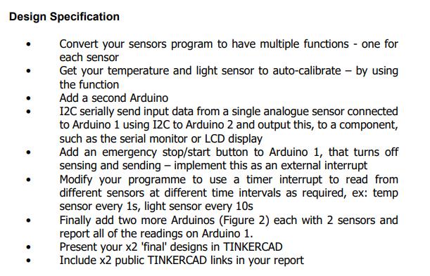
You will design two embedded systems with multiple inputs on one microcontroller and output via a single controller. That employs 12C communication, timer interrupts to sense the data at different times and an external interrupt on microcontroller 1 to stop the sensing. Outputs will be shown on microcontroller 1. This can be viewed in Figure 1 and Figure 2. Use Timer Interrupts to poll sensors at different frequencies Use a button at C1 to stop sensing C 2 using external interrupt Analogue 0-5V I/P #1 ADC #1 Analogue 0-5V I/P #2 12C Communication C 2 ADC #2 Figure 1 initial Embedded System in Hardware and Software Use Timer Interrupts to poll sensors at different frequencies ADC #2:1 HC 2 12C Communication ADC #2:2 Use a 3-way switch at C 1 to stop sensing from each of the uc using external interrupt ADC #3:1 C 1 Analogue 0-5V I/P #2:1 Analogue 0-5V I/P #2:2 Analogue 0-5V I/P #3:1 Analogue 0-5V 1/P #3:2 Analogue 0-5V I/P #4:1 Analogue 0-5V I/P #4:2 C 1 C 3 C 4 12C Communication ADC #3:2 ADC #4:1 12C Communication ADC #4:2 Figure 2 Enhanced Embedded System in Software Digital Output #1 Digital Output #2 Digital Output #1 Digital Output #N Design Specification Convert your sensors program to have multiple functions - one for each sensor Get your temperature and light sensor to auto-calibrate - by using the function Add a second Arduino 12C serially send input data from a single analogue sensor connected to Arduino 1 using I2C to Arduino 2 and output this, to a component, such as the serial monitor or LCD display Add an emergency stop/start button to Arduino 1, that turns off sensing and sending - implement this as an external interrupt Modify your programme to use a timer interrupt to read from different sensors at different time intervals as required, ex: temp sensor every 1s, light sensor every 10s Finally add two more Arduinos (Figure 2) each with 2 sensors and report all of the readings on Arduino 1. Present your x2 'final' designs in TINKERCAD Include x2 public TINKERCAD links in your report
Step by Step Solution
3.41 Rating (148 Votes )
There are 3 Steps involved in it
A relay is a form of form of electrica switch Lin... View full answer

Get step-by-step solutions from verified subject matter experts