

Consider the circuit shown in Figure 7.25(a). The bias voltages are changed to (V^{+}=3 mathrm{~V}) and (V^{-}=-3
Question:
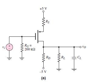
Consider the circuit shown in Figure 7.25(a). The bias voltages are changed to \(V^{+}=3 \mathrm{~V}\) and \(V^{-}=-3 \mathrm{~V}\). The load resistor is \(R_{L}=20 \mathrm{k} \Omega\). The transistor parameters are \(K_{p}=0.1 \mathrm{~mA} / \mathrm{V}^{2}, V_{T P}=-0.6 \mathrm{~V}\), and \(\lambda=0\).
(a) Design the circuit such that \(I_{D Q}=0.2 \mathrm{~mA}\) and \(V_{S D Q}=1.9 \mathrm{~V}\).
(b) Determine the value of \(C_{L}\) that produces a corner frequency of \(f_{H}=4 \mathrm{MHz}\).
Figure 7.25(a):-
Fantastic news! We've Found the answer you've been seeking!
Step by Step Answer:

Answered By
Joan Gakii
I'm a meticulous professional writer with over five years writing experience. My skill set includes
- Digital Content,
- Interpersonal Communication,
- Web Content and academic Writing,
- Proofreading,
- Editing,
- Project Management, and
- Public Relations.
7+ Reviews
12+ Question Solved
Related Book For 

Microelectronics Circuit Analysis And Design
ISBN: 9780071289474
4th Edition
Authors: Donald A. Neamen
Question Posted:
