

Question: Given the data for the three parallel pipes in Figure 4.20 , compute (1) the equivalent parallel pipe coefficient, (2) the head loss between nodes
Given the data for the three parallel pipes in Figure 4.20 , compute (1) the equivalent parallel pipe coefficient, (2) the head loss between nodes A and B, (3) the flow rates in each pipe, (4) the total head at node B, and (5) the diameter of an equivalent pipe with length 100 m and Chw = 100.
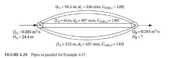
QA=0.283 m/s HA = 24.4 m (L = 91.5 m, d = 356 mm, CHW,1 = 120) (L2=61m, d2=407 mm, CHW,2 = 130) B QB = 0.283 m/s HB = ? (L3 122 m, d3 457 mm, CHW,3 = 110) FIGURE 4.20 Pipes in parallel for Example 4.17.
Step by Step Solution
3.37 Rating (169 Votes )
There are 3 Steps involved in it
1 The equivalent parallel pipe coefficient allows us to determine the head loss that can then be use... View full answer

Get step-by-step solutions from verified subject matter experts