

In the common-base circuit shown in Figure P7.70, the transistor parameters are: (beta=100, V_{B E}() on ()=0.7
Question:
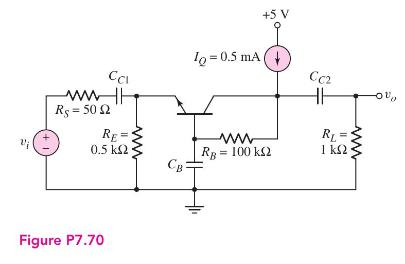
In the common-base circuit shown in Figure P7.70, the transistor parameters are: \(\beta=100, V_{B E}(\) on \()=0.7 \mathrm{~V}, V_{A}=\infty, C_{\pi}=10 \mathrm{pF}\), and \(C_{\mu}=1 \mathrm{pF}\).
(a) Determine the upper \(3 \mathrm{~dB}\) frequencies corresponding to the input and output portions of the equivalent circuit.
(b) Calculate the small-signal midband voltage gain.
(c) If a load capacitor \(C_{L}=15 \mathrm{pF}\) is connected between the output and ground, determine if the upper \(3 \mathrm{~dB}\) frequency will be dominated by the \(C_{L}\) load capacitor or by the transistor characteristics.
Fantastic news! We've Found the answer you've been seeking!
Step by Step Answer:

Answered By
Piyush Kalyankar
I am pursuing for graduation in Mathematics.
0 Reviews
10+ Question Solved
Related Book For 

Microelectronics Circuit Analysis And Design
ISBN: 9780071289474
4th Edition
Authors: Donald A. Neamen
Question Posted:
