

The bridge circuit in Figure P11.27 is a temperature transducer in which the resistor (R_{A}) is a
Question:
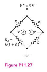
The bridge circuit in Figure P11.27 is a temperature transducer in which the resistor \(R_{A}\) is a thermistor (a resistor whose resistance varies with temperature). The value of \(\delta\) varies over the range of \(-0.01 \leq \delta \leq 0.01\) as temperature varies over a particular range. Assume the value of \(R=40 \mathrm{k} \Omega\). The bridge circuit is to be connected to the diff-amp in Figure 11.2. The diff-amp circuit parameters are \(V^{+}=5 \mathrm{~V}, V^{-}=-5 \mathrm{~V}, I_{Q}=0.2 \mathrm{~mA}\), and \(R_{C}=15 \mathrm{k} \Omega\). The transistor parameters are \(\beta=120, V_{B E}(\mathrm{on})=0.7 \mathrm{~V}\), and \(V_{A}=\infty\). Terminal A of the bridge circuit is connected to the base of \(Q_{1}\) and terminal B is connected to the base of \(Q_{2}\). Determine the range of output voltage \(v_{O 2}\) as \(\delta\) changes.
Step by Step Answer:


Microelectronics Circuit Analysis And Design
ISBN: 9780071289474
4th Edition
Authors: Donald A. Neamen
