

Question: The circuit parameters for the diff-amp shown in Figure 11.30 are (V^{+}=3.3 mathrm{~V}, V^{-}=-3.3 mathrm{~V}), and (I_{Q}=0.4 mathrm{~mA}). The transistor parameters are (beta=120, V_{A 1}=V_{A
The circuit parameters for the diff-amp shown in Figure 11.30 are \(V^{+}=3.3 \mathrm{~V}, V^{-}=-3.3 \mathrm{~V}\), and \(I_{Q}=0.4 \mathrm{~mA}\). The transistor parameters are \(\beta=120, V_{A 1}=V_{A 2}=120 \mathrm{~V}, V_{A 3}=V_{A 4}=80 \mathrm{~V}\), and \(V_{A 5}=\infty\).
(a) Determine the open-circuit differential-mode voltage gain.
(b) What is the output resistance of the diff-amp?
(c) Find the value of load resistance \(R_{L}\) that reduces the differential-mode gain to 75 percent of the open-circuit value.
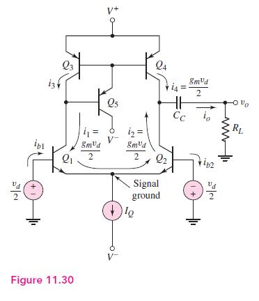
22 13 Q3 V+ Q5 12= Q4 i4= 8mvd 2 Vo Cc RL ipl 8mvd 8mvd 2 2 Q2 ip2 Signal + ground +1 Figure 11.30
Step by Step Solution
There are 3 Steps involved in it

Get step-by-step solutions from verified subject matter experts